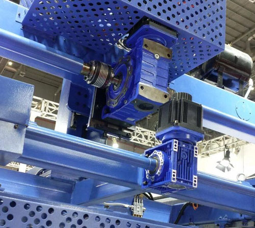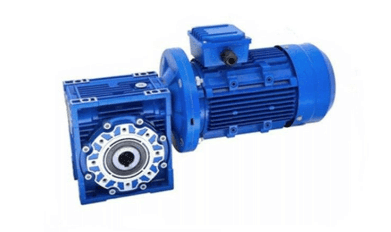
The NMRV130 worm gear reducer is a common industrial transmission component, featuring a compact design and low noise. This type of reducer is typically used in applications requiring a large reduction ratio and torque. Below is a summary of some NMRV130 reducer models and related information:
Based on reduction ratio: Reduction ratio: The NMRV130 reducer is available in a variety of reduction ratios, such as 10 and 40. Specific models include the NMRV130-10, NMRV130-40, and NMRV130-50.
Based on power and application: Power: The NMRV130 reducer can be matched with different motor powers, such as 4kW and 5.5kW. Specific models: For examples NMRV130-50-4kW and NMRV130-50-5.5kW.
Other characteristics: Mounting Type: Horizontal. Layout: Three-ring or angled. Tooth Hardness: Hardened. Permissible Torque: Depending on the reduction ratio, the allowable torque may vary, such as 264 Nm. Input Speed: Generally, the input speed of a reducer can vary within a certain range, such as 1420 rpm. Output Speed: Calculated based on the reduction ratio, such as 300-14 rpm.
The specific model of the NMRV130 worm gear reducer varies depending on the manufacturer, application requirements, and other factors. If you require more detailed model information or application-specific recommendations, please contact our dedicated sales team directly to provide the best solution for your needs.
Configuring the performance parameters of the NMRV130 worm gear reducer to meet the requirements of your machinery requires consideration of several factors. Here are some basic steps and considerations:
1. Define the Application Requirements First, determine the type of machinery the reducer will be used for and the operating conditions of that machinery. For example, will it be used on a conveyor belt, packaging machinery, or other type of industrial equipment?
2. Determine the Load Conditions Load Type: Determine whether it is continuous or intermittent. Load Size: Calculate the maximum load torque during operation.
3. Calculate the Required Reduction Ratio The reduction ratio (i) is a key parameter of a reducer, determining the ratio between input speed and output speed.
4. Input and Output Parameters Input power: Typically provided by the motor, ensure the reducer can handle this power without overloading. Input speed: The rated speed of the motor. Output speed: Determined based on the operating requirements of the mechanical equipment. Output torque: Calculated based on the reduction ratio and input power.
5. Determine the mounting method Mounting position: Determine whether the gear reducer will be mounted vertically or horizontally. Interface type: Determine the input and output interface types, including whether special couplings or flanges are required.
6. Select the appropriate model Based on the above parameters, select the NMRV130 model that meets your requirements. For example, if higher torque and lower output speed are required, a model with a larger reduction ratio can be selected.
7. Check Environmental Conditions Consider the environmental conditions in which the reducer will operate, such as temperature, humidity, and the presence of corrosive gases, and select a product with the appropriate level of protection.
8. Consider Maintenance Ease Select a design that facilitates maintenance, including lubricant changes and wear inspections.
9. Safety Factor To ensure the safety and reliability of the mechanical system, a safety factor is typically added to the calculated parameters.
Notes During the configuration process, ensure that the performance parameters of the selected reducer meet the requirements of the machine and allow for sufficient margin. If you are unsure how to select the appropriate reducer, it is best to consult a professional engineer or manufacturer.
The above steps will provide a comprehensive guide to configuring an NMRV130 worm gear reducer for your specific machine. In actual operation, you will also need to refer to the specific machine design manual and technical specifications to make the final decision.
The NMRV130 worm gear reducer is a commonly used industrial transmission device. Some components may experience wear over time. The following are the main components susceptible to wear:
Worm wheel and worm shaft: These two components are the core transmission components of the NMRV reducer. Contact and friction between them cause wear. The material and surface finish of the worm wheel and worm shaft directly affect their service life.
Bearings: The bearings within a gearbox support the worm shaft or other rotating components. Due to the long-term rotational loads they bear, bearings are susceptible to wear, especially if lubrication is poor.
Gearbox Housing: Although the housing itself is not susceptible to wear, in some cases, such as improper installation leading to misalignment or external impact, the fixed points within the housing may be affected, thereby affecting the proper operation of internal components.
Seals: Seals prevent lubricant leakage and foreign matter from entering the reducer. Over time, seals may age, harden, or become damaged, losing their sealing effectiveness.
Oil Seals: Oil seals primarily protect the lubricant within the reducer from leaking out and prevent the entry of dust and other foreign matter. Failure of the oil seal can lead to lubricant loss and contamination, accelerating wear of internal components.
Couplings: If a coupling is used between the reducer and motor, it can also wear out due to misalignment or overload.
In order to extend the service life of the NMRV130 worm gear reducer, regular maintenance is very important. This includes but is not limited to regularly checking the quality and quantity of lubricating oil, checking and adjusting the alignment of various components, and timely replacement of worn parts. In addition, the correct installation and rational use of the reducer is also the key to reducing wear.