
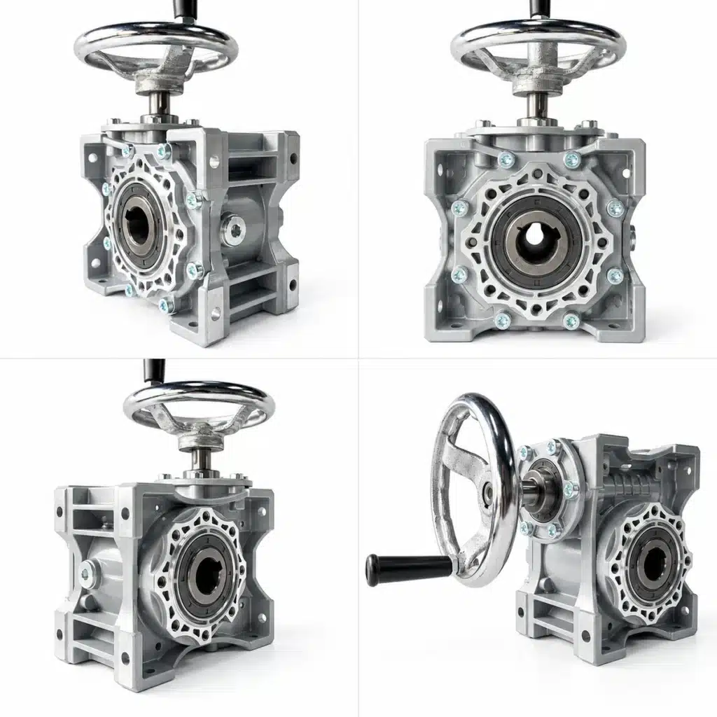
Hand Crank Gearbox: Self-Locking Worm Gear Solution for Manual Turning
Not every industrial motion system needs an electric motor. For equipment that only requires occasional turning, tilting, positioning, or emergency movement, a hand crank gearbox can provide a simple, reliable, and cost-effective solution.
A manual worm gearbox uses a handwheel or crank to drive a worm gear reduction mechanism. The high reduction ratio converts manual rotation into slow, controlled output movement with increased torque. In suitable worm gear configurations, the transmission can also resist back-driving, providing a self-locking effect that helps hold the load in position.
This makes hand-operated worm gearboxes particularly suitable for feed bin tilting, mold and plate turning platforms, conveyor chain positioning, material handling equipment, and other industrial manual adjustment mechanisms.
What Is a Hand Crank Gearbox?
A hand crank gearbox is a manually operated reduction gearbox that transfers the rotation of a handwheel or crank to an output shaft or hollow bore.
Instead of using an electric motor, the operator provides the input force manually. Inside a worm-type hand crank gearbox, the worm shaft drives the worm wheel at a reduced speed.
In simple terms:
Manual Handwheel → Worm Shaft → Worm Wheel → Low-Speed, High-Torque Output
Because the gearbox provides mechanical reduction, the operator can control relatively heavy loads with less input effort than would be required with a direct-drive mechanism.
This makes a handwheel gearbox particularly useful where movement is intermittent and precise manual control is more important than continuous automatic operation.
How Does a Hand Crank Worm Gearbox Work?
The working principle is based on a worm and worm wheel transmission.
When the operator rotates the handwheel, the input shaft turns the worm. The worm then drives the mating worm wheel, reducing rotational speed while increasing available output torque.
For example, a high reduction ratio means that multiple rotations of the handwheel produce a much smaller rotation at the output. This allows the operator to move a platform, hopper, conveyor mechanism, or other equipment gradually and with good positional control.
The right-angle arrangement of a typical worm gear reducer also provides a compact transmission layout, which can be advantageous when installation space is limited.
Why Use a Self-Locking Worm Gearbox?
One of the most useful characteristics of a worm drive for manual operation is its potential resistance to reverse driving.
In an appropriately designed self-locking worm gearbox, the operator can rotate the handwheel to move the load, while the load has greater difficulty driving the gearbox backward after manual input stops.
This characteristic can provide several practical benefits:
- Helps hold equipment at the required position
- Reduces unintended reverse movement
- Can simplify the mechanical drive system
- May eliminate the need for a separate brake in suitable applications
- Provides controlled manual positioning without electrical power
This is particularly useful for tilting and positioning mechanisms where the equipment needs to remain at a selected angle or position.
Important: Not every worm gearbox is inherently self-locking. Self-locking capability depends on factors including the worm lead angle, reduction ratio, coefficient of friction, lubrication, vibration, load direction, wear, and operating conditions.
For safety-critical lifting, suspended loads, or applications involving personnel, a dedicated brake or mechanical locking device should be considered according to the applicable safety requirements.
Typical Hand Crank Gearbox Applications
Feed Bin and Hopper Tilting
Feed bins, feed barrels, hoppers, and similar containers sometimes need to be manually tilted for unloading, cleaning, inspection, or maintenance.
A manual worm gearbox allows the operator to rotate the container gradually using a handwheel. Where the selected worm drive provides adequate resistance to back-driving, it can also help maintain the required tilting position.
This provides an economical solution for equipment that does not require frequent powered operation.
Mold and Plate Turning Platforms
Industrial molds, metal plates, panels, fixtures, and workpieces may need to be rotated during production, assembly, inspection, or maintenance.
A hand crank worm gearbox can be integrated into a turning platform to provide slow and controlled rotation.
Compared with direct manual rotation, the reduction mechanism increases available torque and gives the operator better control over the movement of the workpiece.
Conveyor Chain Emergency Movement
A conveyor system normally operates with an electric motor, but manual movement may still be required during a power failure, commissioning, maintenance, or troubleshooting.
A hand operated gearbox can provide a mechanical method for slowly repositioning a conveyor chain when electrical drive power is unavailable.
The exact manual drive arrangement should be designed according to the conveyor load, required torque, drive connection, and relevant machinery safety requirements.
Industrial Positioning and Adjustment
Handwheel worm gearboxes can also be used in:
Machine adjustment mechanisms · Gates and dampers · Material handling equipment · Positioning tables · Industrial fixtures · Manual rotating equipment · Packaging machinery · Maintenance mechanisms
They are especially useful when equipment only needs occasional adjustment and installing a complete motorized drive system would add unnecessary cost and complexity.
Hand Crank Gearbox vs. Motorized Gearbox
Choosing between a manual and motorized gearbox depends primarily on operating frequency, automation requirements, load, and positioning needs.
| Feature | Hand Crank Gearbox | Motorized Gearbox |
|---|---|---|
| Power Supply | Not required | Electrical power required |
| Operation | Manual | Automatic / powered |
| Initial Cost | Generally lower | Generally higher |
| Installation | Relatively simple | Requires motor and electrical system |
| Positioning | Operator controlled | Can be automated |
| Best Use | Occasional movement | Frequent or continuous operation |
| Maintenance | Relatively simple | Motor and controls also require maintenance |
| Power Failure Operation | Possible | Requires backup/manual provision |
For equipment that only needs occasional rotation or adjustment, a manual gearbox with handwheel can therefore be a more economical solution.
For high-frequency or automated production equipment, a motorized gearbox will normally be more appropriate.
Advantages of a Hand Operated Worm Gearbox
A properly selected hand crank worm gearbox combines several practical advantages in one compact drive:
No electric motor required — suitable for manual or emergency operation.
High reduction ratio — converts handwheel rotation into slow and controlled output movement.
Higher output torque — mechanical reduction helps the operator move heavier mechanisms with less effort.
Potential self-locking effect — suitable worm drive configurations can resist back-driving.
Compact right-angle design — useful where installation space is limited.
Simple installation — fewer electrical components are required.
Low maintenance requirements — a relatively simple mechanical transmission system.
Competitive cost — economical for intermittent positioning applications.
Fast delivery options — standard worm gearbox sizes and configurations can reduce sourcing lead time.
How to Select the Right Manual Worm Gearbox
Correct gearbox selection is important for reliable and safe operation.
Before selecting a hand crank gearbox, the following parameters should be considered:
1. Required Output Torque
Determine the torque required to rotate, tilt, or reposition the load.
2. Gear Reduction Ratio
A higher reduction ratio reduces output speed and generally makes manual operation easier, but increases the number of handwheel rotations required.
3. Output Shaft or Hollow Bore
The output connection must match the driven shaft and equipment interface.
4. Mounting Arrangement
Consider foot mounting, flange mounting, shaft orientation, available installation space, and gearbox mounting position.
5. Handwheel Diameter
A larger handwheel can provide greater manual leverage but requires more installation space.
6. Load Direction
The direction and nature of the load affect gearbox selection and whether back-driving resistance is required.
7. Operating Frequency
Manual gearboxes are generally most suitable for intermittent positioning rather than high-speed continuous operation.
8. Self-Locking Requirement
If holding the load without reverse movement is important, the specific gearbox configuration must be evaluated for back-driving behavior rather than assuming that every worm reducer is self-locking.
Manual Worm Gearbox Solutions for OEM Machinery
For OEM machine builders, distributors, and industrial equipment manufacturers, a hand crank worm gearbox can be a practical alternative to a motorized drive when the mechanism only requires intermittent movement.
Standard worm gear reducer platforms can be configured with different reduction ratios, hollow bores, output shafts, mounting arrangements, flanges, and manual input mechanisms to suit different equipment designs.
Applications can range from small positioning mechanisms to larger industrial turning and tilting systems.
When selecting a gearbox, the objective should not simply be to choose the highest available ratio. The gearbox, handwheel, shaft connection, mounting arrangement, output torque, and safety requirements should be evaluated as a complete drive system.
Looking for a Hand Crank Gearbox for Your Equipment?
KB Transmission Star supplies worm gear reducers and industrial gearbox solutions for OEM machinery manufacturers, distributors, and industrial users.
If your machine requires manual turning, tilting, positioning, or emergency movement, we can help evaluate a suitable manual worm gearbox configuration based on your application.
For gearbox selection, please provide:
Required output torque · Reduction ratio · Output shaft or hollow bore size · Mounting position · Handwheel requirement · Load direction · Operating frequency · Application description
Contact us with your application requirements to select a suitable hand crank worm gearbox for your equipment.
Frequently Asked Questions About Hand Crank Gearboxes
What is a hand crank gearbox?
A hand crank gearbox is a manually operated reduction gearbox that uses a handwheel or crank instead of an electric motor to provide mechanical input. Worm gear designs are commonly used when an application requires low-speed, high-torque manual turning or positioning.
Can a worm gearbox be operated by hand?
Yes. A worm gearbox can be configured with a handwheel or crank for manual operation. This arrangement is suitable for intermittent turning, tilting, positioning, adjustment, and certain emergency manual movement applications.
Is a hand crank worm gearbox self-locking?
Some worm gear configurations can provide a self-locking or non-backdriving effect, but not every worm gearbox is self-locking. Actual behavior depends on the reduction ratio, worm lead angle, friction, lubrication, vibration, load, wear, and other operating conditions.
Where are manual worm gearboxes used?
Typical applications include feed bin and hopper tilting, mold and plate turning platforms, conveyor positioning, material handling equipment, gates, adjustment mechanisms, industrial fixtures, and machinery requiring occasional manual movement.
How do I select the right hand crank gearbox?
Selection should consider required output torque, reduction ratio, shaft or hollow bore dimensions, mounting position, handwheel diameter, load direction, operating frequency, available installation space, and whether resistance to back-driving is required.