Description
KB Transmission Star — Industrial Worm Gearbox Manufacturer & OEM Supplier
NMRV Worm Gearboxes for Industrial OEMs, Distributors & Replacement Applications
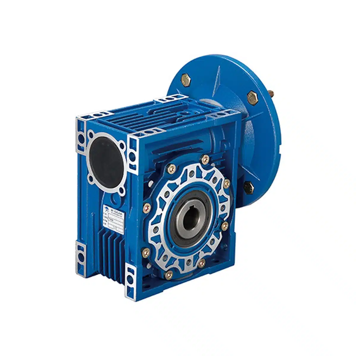
KB Transmission Star manufactures and supplies NMRV worm gear reducers in 11 frame sizes, from NMRV025 to NMRV150, for industrial machinery, conveyor systems, packaging equipment and OEM power transmission applications.
Our NMRV gearboxes combine compact right-angle transmission, standardized hollow output bores, IEC motor interfaces and flexible mounting configurations.
We support machinery manufacturers, industrial gearbox distributors and maintenance teams with model selection, technical drawings, replacement verification and factory quotations.
Key Product Specifications
| Specification | NMRV Product Range |
|---|---|
| Models | NMRV025–NMRV150 |
| Frame sizes | 11 |
| Standard ratios | 7.5:1–100:1 across the series |
| Motor power | 0.06–15 kW across the series |
| Standard output bores | Ø11–Ø50 H8 |
| Housing materials | Aluminum alloy / Cast iron |
| Input | IEC motor flange options |
| Output | Keyed hollow bore, optional output flanges and solid output shaft configurations |
| Double reduction | NMRV/NMRV combinations |
| Applications | Conveyors, packaging, food-processing machinery and industrial automation |
Ratio, power and mounting availability depend on the selected gearbox size and configuration.
Request a Factory Quotation | Get Technical Selection Support
1. What Is an NMRV Worm Gear Reducer?
An NMRV worm gear reducer is a compact right-angle gearbox that uses a hardened steel worm and mating bronze worm wheel to reduce motor speed and transmit torque.
The worm shaft drives the worm wheel through sliding tooth contact, producing a high reduction ratio within a relatively compact housing.
NMRV worm gearboxes are widely used where installation space, shaft orientation, reduction ratio and initial equipment cost are important selection factors.
Key Advantages
Compact Right-Angle Transmission
The motor input and gearbox output are arranged at approximately 90 degrees, allowing flexible machine layouts.
Multiple Reduction Ratios
The NMRV series provides a range of standard single-stage reduction ratios for different output-speed requirements.
Flexible Mounting
Available configurations include hollow output bores, output flanges and optional solid output shaft arrangements.
IEC Motor Compatibility
Selected gearbox sizes can be configured with IEC motor adapters for standard industrial motors.
OEM and Replacement Applications
Standardized frame sizes and documented dimensions support new equipment design and replacement evaluation.
2. NMRV025–150 Technical Specifications
| Parameter | Specification |
|---|---|
| Product type | Worm gear reducer |
| Gear arrangement | Worm and worm wheel |
| Shaft arrangement | Right-angle transmission |
| Frame sizes | 025, 030, 040, 050, 063, 075, 090, 105, 110, 130, 150 |
| Nominal center distance | 25–150 mm |
| Ratio series | 7.5, 10, 15, 20, 25, 30, 40, 50, 60, 80, 100 |
| Motor power range | 0.06–15 kW across the family |
| Housing material, 025–105 | Aluminum alloy |
| Housing material, 110–150 | Cast iron |
| Worm shaft | 20Cr alloy steel, carburized and hardened |
| Worm surface hardness | 56–62 HRC |
| Carburized case depth | 0.3–0.5 mm |
| Worm wheel | Tin bronze |
| Standard output | Keyed hollow bore |
| Output options | Output flanges and selected solid shaft arrangements |
| Motor interface | IEC motor-adapter options |
| Multi-stage options | NMRV/NMRV, PC-NMRV, UDL-NMRV |
Individual gearbox models do not necessarily support every listed ratio or motor-power combination.
Final selection depends on output torque, service factor, radial load, thermal capacity and installation requirements.
3. NMRV Model Sizes, Hollow Bore Dimensions & Keyways
The NMRV025–150 range includes 11 gearbox frame sizes.
The table below provides the standard hollow output bore and keyway width for each model.
| Model | Center Distance | Standard Hollow Bore | Keyway Width | Housing |
|---|---|---|---|---|
| NMRV025 | 25 mm | Ø11 H8 | 4 mm | Aluminum |
| NMRV030 | 30 mm | Ø14 H8 | 5 mm | Aluminum |
| NMRV040 | 40 mm | Ø18 H8 | 6 mm | Aluminum |
| NMRV050 | 50 mm | Ø25 H8 | 8 mm | Aluminum |
| NMRV063 | 63 mm | Ø25 H8 | 8 mm | Aluminum |
| NMRV075 | 75 mm | Ø28 H8 | 8 mm | Aluminum |
| NMRV090 | 90 mm | Ø35 H8 | 10 mm | Aluminum |
| NMRV105 | 105 mm | Ø42 H8 | 12 mm | Aluminum |
| NMRV110 | 110 mm | Ø42 H8 | 12 mm | Cast iron |
| NMRV130 | 130 mm | Ø45 H8 | 14 mm | Cast iron |
| NMRV150 | 150 mm | Ø50 H8 | 14 mm | Cast iron |
For detailed model selection, visit our NMRV Complete Model Guide.
4. NMRV Reduction Ratios & Output Speed
The NMRV worm gear reducer series offers the following standard nominal reduction ratios:
7.5:1, 10:1, 15:1, 20:1, 25:1, 30:1, 40:1, 50:1, 60:1, 80:1 and 100:1.
Not all ratios are available for every frame size.
How to Calculate the Reduction Ratio
Reduction ratio = Input speed ÷ Output speed
i = n1 / n2
Where:
-
i = Reduction ratio
-
n1 = Input speed in rpm
-
n2 = Output speed in rpm
Example
Input speed: 1,400 rpm
Required output speed: 35 rpm
Reduction ratio = 1,400 / 35 = 40
The nominal gearbox ratio is 40:1.
The selected gearbox must also satisfy the required output torque, service factor and thermal conditions.
Double Reduction NMRV Gearboxes
For applications requiring very low output speeds, two NMRV gearboxes can be connected in series.
Overall reduction ratio = First-stage ratio × Second-stage ratio
i_total = i1 × i2
For example:
30 × 60 = 1,800
This produces a nominal total reduction ratio of 1,800:1.
Selected double-reduction configurations can provide overall ratios around 5,000:1, subject to the available stage combinations and engineering limits.
Read our NMRV50/110 1800:1 Technical Case Study.
Explore our Double Reduction Gearbox Range.
5. NMRV Gearbox Performance & Torque Selection
The required gearbox size depends on motor power, reduction ratio, output torque, operating hours and application service factor.
The following technical data illustrates the performance differences between selected gearbox sizes at the same nominal motor power and reduction ratio.
Performance Example — 1.5 kW, 60:1
| Model | Motor Power | Ratio | Output Speed | Output Torque | Reference Radial Load | Catalog Service Factor |
|---|---|---|---|---|---|---|
| NMRV090 | 1.5 kW | 60:1 | 23.3 rpm | 417 Nm | 6,163 N | 0.8 |
| NMRV105 | 1.5 kW | 60:1 | 23.3 rpm | 442 Nm | 7,787 N | 1.2 |
| NMRV110 | 1.5 kW | 60:1 | 23.3 rpm | 442 Nm | 7,787 N | 1.4 |
These values apply to the specified gearbox and motor combinations, not to every configuration within each frame size.
How to Interpret the Catalog Service Factor
The catalog service factor (fs) expresses the available torque reserve for a specified gearbox and motor combination under the KB rating method.
For preliminary comparison:
Approximate rated output torque = Listed output torque × Catalog service factor
M2n ≈ M2 × fs
For NMRV105:
442 Nm × 1.2 = 530.4 Nm
| Model | Listed Output Torque | Catalog Service Factor | Approximate Rated Output Torque |
|---|---|---|---|
| NMRV090 | 417 Nm | 0.8 | 334 Nm |
| NMRV105 | 442 Nm | 1.2 | 530 Nm |
| NMRV110 | 442 Nm | 1.4 | 619 Nm |
These values are approximate calculations derived from the listed output torque and catalog service factor. Final selection must follow the applicable KB rated-torque data.
Understanding a Catalog Service Factor Below 1.0
A catalog service factor below 1.0 means the listed motor can deliver more torque than the gearbox’s rated output torque at that reduction ratio.
However, this does not automatically mean the gearbox is unsuitable for every application.
The actual application service factor should be calculated by comparing the gearbox’s rated output torque with the torque required by the driven machine.
Actual application service factor = Gearbox rated output torque / Actual load torque
fs_eff = M2n / Mload
For example, the NMRV090 at 1.5 kW and 60:1 has a catalog service factor of 0.8 and an approximate rated output torque of 334 Nm.
If the actual load torque is 320 Nm:
Actual application service factor = 334 / 320 ≈ 1.04
This may be sufficient for an application requiring a service factor of 1.0, but it would not satisfy an application requiring a service factor of 1.5.
If the required service factor is higher than the available service factor, select a gearbox with a higher rated output torque, such as a larger frame size or another suitable configuration.
A smaller motor does not increase the gearbox’s rated torque, but it may reduce the maximum torque available to the gearbox when the originally selected motor has excess torque capacity.
Final selection must also account for radial loads, thermal capacity, operating hours and starting conditions.
6. How to Select the Correct NMRV Worm Gear Reducer
Selecting an NMRV gearbox requires more than matching the motor power and reduction ratio.
The gearbox must also accommodate the actual load characteristics and operating conditions.
Step 1 — Identify the Application
Confirm whether the gearbox will drive a conveyor, packaging machine, mixer, feeder or another industrial mechanism.
Step 2 — Determine the Load Classification
The KB technical selection system distinguishes three general driven-machine load categories.
| Load Class | Load Characteristics | Typical Selection Considerations |
|---|---|---|
| A | Uniform or relatively steady loading | Operating hours and starting frequency |
| B | Moderate load fluctuations | Starting load, duty cycle and service factor |
| C | Heavy shock or strongly fluctuating loads | Peak torque, repeated starts and thermal capacity |
The required service factor depends on the driven machine, daily operating hours and starts per hour.
Step 3 — Confirm Motor Power and Input Speed
Record the rated motor power, actual operating speed, motor frame and flange configuration.
Step 4 — Calculate the Reduction Ratio
i = n1 / n2
Choose the nearest suitable standard ratio and verify the resulting output speed.
Step 5 — Calculate Output Torque
Output torque (Nm) = 9550 × Input power (kW) × Efficiency ÷ Output speed (rpm)
M2 = (9550 × P1 × η) / n2
Where:
-
M2 = Output torque in Nm
-
P1 = Input power in kW
-
η = Gearbox efficiency
-
n2 = Output speed in rpm
Step 6 — Apply the Required Service Factor
Required rated output torque:
M2n ≥ Mload × fs_required
Where:
-
M2n = Gearbox rated output torque
-
Mload = Actual application load torque
-
fs_required = Application-required service factor
Step 7 — Verify Mechanical & Thermal Limits
Check output radial load, mounting dimensions, lubrication arrangement, thermal performance and motor compatibility.
For more information, read our Worm Gear Reducer Torque Calculation Guide.
KB Technical Selection Example — NMRV075
The following example demonstrates how operating duty and service-factor corrections affect motor and gearbox selection.
| Parameter | Value |
|---|---|
| Required machine output power | 0.5 kW |
| Input speed | 1,400 rpm |
| Required output speed | 93.3 rpm |
| Reduction ratio | 15:1 |
| Starts per hour | 20 |
| Daily operating time | 24 hours |
| Ambient temperature | 32°C |
| Estimated gearbox efficiency | 0.82 |
| Corrected service factor | 1.714 |
| Calculated required motor power | 1.045 kW |
| Selected motor power | 1.1 kW |
| Selected gearbox | NMRV075-15-B3-1.1-4 |
| Required output torque | 51.18 Nm |
| Service-factor-adjusted torque | 87.72 Nm |
| Selected rated gearbox torque | 95 Nm |
Calculation
Required motor power = (0.5 / 0.82) × 1.714 = 1.045 kW
Required output torque = (9550 × 0.5) / 93.3 = 51.18 Nm
Service-factor-adjusted torque = 51.18 × 1.714 = 87.72 Nm
The selected NMRV075 configuration provides a rated output torque of 95 Nm for this example.
The example illustrates how load conditions can justify selecting a motor larger than the machine’s nominal output-power requirement.
For conveyor applications, see our Worm Gear Reducer for Conveyor Systems Selection Guide.
7. Output Shaft Radial Load Calculation
External transmission components such as sprockets, pulleys and gears can apply radial forces to the gearbox output shaft.
These forces must be considered when selecting the gearbox size and output shaft configuration.
Radial Load Formula
Radial load = 2000 × Output torque × Transmission factor ÷ Transmission diameter
Fr = (2000 × M × fz) / d0
Where:
-
Fr = Calculated radial load (N)
-
M = Output shaft torque (Nm)
-
fz = Transmission-element factor
-
d0 = Mean diameter of the transmission element (mm)
Transmission-Element Factors
| Transmission Element | Condition | Factor fz |
|---|---|---|
| Gear | 17 or more teeth | 1.00 |
| Gear | Fewer than 17 teeth | 1.15 |
| Chain sprocket | 20 or more teeth | 1.00 |
| Chain sprocket | 13–19 teeth | 1.25 |
| Chain sprocket | Fewer than 13 teeth | 1.40 |
| Narrow V-belt pulley | Including belt tension | 1.75 |
| Flat-belt pulley | Including belt tension | 2.50 |
| Timing-belt pulley | Including belt tension | 2.50 |
Radial Load Calculation Example
Assume:
-
Output torque: 320 Nm
-
Chain sprocket mean diameter: 200 mm
-
Transmission factor: 1.25
Fr = (2000 × 320 × 1.25) / 200
Calculated radial load = 4,000 N
The calculated radial load must be compared with the permissible load for the selected gearbox and actual shaft-load position.
NMRV Output Shaft Radial Load Reference
| NMRV Model | a (mm) | b (mm) | Reference Fr2 max (N) |
|---|---|---|---|
| NMRV025 | 50 | 38 | 1,350 |
| NMRV030 | 65 | 50 | 1,830 |
| NMRV040 | 84 | 64 | 3,490 |
| NMRV050 | 101 | 76 | 4,840 |
| NMRV063 | 120 | 95 | 6,270 |
| NMRV075 | 131 | 101 | 7,380 |
| NMRV090 | 162 | 122 | 8,180 |
| NMRV105 | 176 | 136 | 12,000 |
| NMRV110 | 176 | 136 | 12,000 |
| NMRV130 | 188 | 148 | 13,500 |
| NMRV150 | 215 | 174 | 18,000 |
The reference maximum radial loads do not apply universally to every speed, ratio or shaft configuration. The permissible Fr2 value must be selected for the actual gearbox operating conditions.
Radial Load Position Correction
When the radial force acts at a different position along the output shaft, the permissible load must be corrected.
Permissible load at position x = Applicable radial load × a ÷ (b + x)
FxL ≤ (Fr2 × a) / (b + x)
Where:
-
FxL = Permissible radial load at the specified position (N)
-
Fr2 = Applicable radial-load value (N)
-
a, b = Model-specific dimensional constants (mm)
-
x = Load-position distance defined by the output shaft arrangement (mm)
The formula applies to the relevant shaft arrangement and load-position definition in KB technical data. Other output configurations require separate verification.
8. NMRV Critical Dimensions for Installation & Replacement
Correct gearbox installation requires verification of the output interface, motor adapter, housing mounting dimensions and selected output flange.
KB Transmission Star provides dimensional information for individual gearbox configurations to support OEM equipment design and replacement projects.
NMRV075–110 Critical Installation Dimensions
| Dimension | NMRV075 | NMRV090 | NMRV105 | NMRV110 |
|---|---|---|---|---|
| Standard hollow output bore | Ø28 H8 | Ø35 H8 | Ø42 H8 | Ø42 H8 |
| Output keyway width | 8 mm | 10 mm | 12 mm | 12 mm |
| Keyway-related dimension t1 | 31.3 mm | 38.3 mm | 45.3 mm | 45.3 mm |
| Housing height, illustrated orientation | 205 mm | 238 mm | 295 mm | 295 mm |
| Housing mounting thread | M8 × 14 | M10 × 18 | M10 × 18 | M10 × 18 |
| Optional type E worm-shaft extension diameter | Ø24 j6 | Ø24 j6 | Ø28 j6 | Ø28 j6 |
NMRV Output Flange Pilot Dimensions
| Model | FA Flange Pilot | FB Flange Pilot |
|---|---|---|
| NMRV075 | Ø130 H8 | Ø110 H8 |
| NMRV090 | Ø152 H8 | Ø180 H8 |
| NMRV105 | Ø170 H8 | Ø170 H8 |
| NMRV110 | Ø170 H8 | Ø170 H8 |
Installation Note: Verify the flange pilot diameter, bolt-circle diameter, bolt-hole arrangement and flange thickness against the KB dimensional drawing for the exact ordered flange configuration.
Understanding Keyway Dimension t1
The t1 dimension is the bore-and-keyway measurement specified in KB dimensional drawings.
For the illustrated hollow-bore keyway arrangement:
Nominal radial keyway depth = t1 − Nominal bore diameter
| Model | Hollow Bore | t1 Dimension | Calculated Nominal Keyway Depth |
|---|---|---|---|
| NMRV075 | Ø28 H8 | 31.3 mm | 3.3 mm |
| NMRV090 | Ø35 H8 | 38.3 mm | 3.3 mm |
| NMRV105 | Ø42 H8 | 45.3 mm | 3.3 mm |
| NMRV110 | Ø42 H8 | 45.3 mm | 3.3 mm |
These calculated values are nominal dimensions. Final machining and inspection must follow the approved KB dimensional drawing and applicable tolerances.
Motor Input Interface
Selected NMRV gearboxes support IEC motor adapters.
For example, the NMRV105 configuration with an IEC 132B5 motor adapter uses a Ø38 mm motor-side input bore.
Motor-side dimensions and gearbox output dimensions must be identified separately during installation and replacement checks.
Request KB Dimensional Drawings
Send us the required NMRV model, motor frame, output flange type and mounting arrangement. Our engineering team can help verify the mechanical interface before ordering.
Request KB Dimensional Drawings
9. Worm Shaft Materials, Bronze Worm Wheel & Manufacturing Quality
Hardened 20Cr Alloy-Steel Worm
KB Transmission Star NMRV worm gear reducers use 20Cr alloy-steel worms with a carburized and hardened tooth surface to improve wear resistance and durability.
Worm Shaft Specifications
| Parameter | Specification |
|---|---|
| Worm material | 20Cr alloy steel |
| Surface hardness | 56–62 HRC |
| Carburized case depth | 0.3–0.5 mm |
| Surface treatment | Carburizing and hardening |
| Mating worm wheel | Tin bronze |
The hardened worm and bronze worm wheel are designed to operate together under sliding-contact conditions.
Bronze Worm Wheel
The mating tin-bronze worm wheel provides the bearing and sliding-contact characteristics required for worm gear transmission.
Correct gear contact, lubrication and operating conditions are essential for long-term durability.
Precision-Machined Gearbox Housing
NMRV025–105 gearboxes use aluminum-alloy housings, while NMRV110–150 gearboxes use cast-iron housings.
The housing supports shaft alignment, bearing installation and the mechanical mounting interface.
Manufacturing Quality Control
Critical quality-control considerations include worm heat treatment, gear contact accuracy, shaft alignment, bearing installation, housing tolerances, sealing and lubrication.
OEM Technical Documentation
KB Transmission Star supports OEM manufacturers and industrial distributors with dimensional drawings, material specifications, technical selection and project-specific quality documentation.
10. NMRV Gearbox Configurations
Standard Single-Stage NMRV
A compact worm gear reducer for industrial right-angle speed reduction.
Suitable for applications where the selected ratio, torque capacity and operating duty fall within the gearbox rating.
NMRV/NMRV Double Reduction
Two worm reduction stages connected in series to achieve a much higher overall reduction ratio.
This configuration is suitable for selected low-speed applications, subject to torque, service-factor and thermal verification.
PC-NMRV Helical-Worm Combination
A helical pre-stage combined with an NMRV worm reduction stage.
The available ratios and power ratings depend on the selected combination.
UDL-NMRV Speed Variator Combination
A mechanical speed variator combined with an NMRV gearbox for applications requiring adjustable operating speed.
The configuration must be selected according to the required speed range, load and duty cycle.
11. Installation, Lubrication & Self-Locking
Mounting Position
NMRV worm gearboxes can be configured for different installation orientations.
The correct mounting arrangement must account for lubricant quantity, breather position, shaft loading and maintenance access.
Lubrication
Worm gearing involves significant sliding contact between the worm and worm wheel.
Lubrication is therefore important for reducing wear, controlling temperature and maintaining transmission performance.
Use the lubricant specification and fill quantity appropriate to the selected gearbox and mounting orientation.
Is an NMRV Worm Gearbox Self-Locking?
Some worm gear reducers can resist reverse driving under certain conditions, but self-locking is not guaranteed for every NMRV gearbox.
Back-driving behavior depends on several factors:
-
Worm lead angle and reduction ratio
-
Gear tooth geometry
-
Lubrication and friction
-
Temperature
-
External load
-
Vibration
-
Gear wear and operating conditions
Static vs Dynamic Back-Driving
A gearbox may resist reverse movement while stationary but behave differently when the load is moving or subjected to vibration.
For lifting, suspended loads, personnel safety or other safety-critical applications, use a separately engineered holding brake or appropriate safety device.
Do not rely on assumed worm gearbox self-locking as the sole method of load retention.
Read our Worm Gearbox Maintenance Guide.
12. Industrial Applications of NMRV Worm Gear Reducers
KB Transmission Star NMRV gearboxes are suitable for industrial machinery where compact right-angle transmission and controlled output speed are required.
Conveyor Systems
NMRV gearboxes can drive belt conveyors, roller conveyors and chain conveyor mechanisms.
Selection considerations include conveyor load, output torque, operating hours, starting frequency and output shaft radial load.
Packaging Machinery
NMRV worm reducers can be used in packaging conveyors, feeders, transfer mechanisms and auxiliary machine drives.
Food Processing Equipment
Typical applications include food handling conveyors, packaging lines and auxiliary transmission equipment.
Lubrication, sealing and environmental requirements must be evaluated for the specific installation.
Industrial Automation
NMRV gearboxes are suitable for selected positioning, adjustment and low-speed drive mechanisms.
Material Handling Equipment
Applications may include powered rollers, transfer equipment and general machinery requiring right-angle speed reduction.
For continuous-duty or high-efficiency requirements, compare the operating characteristics of worm, helical and hypoid gearboxes before selecting the final drive.
13. NMRV Worm Gearbox vs Helical Gearbox
NMRV worm gear reducers and helical gearboxes serve different industrial transmission requirements.
The correct choice depends on installation layout, reduction ratio, operating efficiency, load characteristics and total operating cost.
| Engineering Factor | NMRV Worm Gearbox | Helical Gearbox |
|---|---|---|
| Shaft arrangement | Compact right-angle drive | Commonly inline or parallel-shaft |
| Gear contact | Significant sliding contact | Predominantly rolling/meshing tooth contact |
| Efficiency | Depends on ratio, size, speed and loading | Generally higher in comparable applications |
| Thermal performance | Requires careful checking for continuous duty | Often advantageous for high-efficiency continuous duty |
| Reduction ratio | High single-stage ratios available | High ratios generally require multiple stages |
| Installation | Compact for many right-angle applications | Depends on gearbox configuration |
| Typical selection priority | Right-angle layout, compactness and initial cost | Efficiency and sustained-duty performance |
Which Gearbox Is Better for a Conveyor?
NMRV can be a practical choice for compact conveyors with moderate loads and limited installation space.
Helical gearboxes may be preferable for continuous-duty conveyors where efficiency and operating cost are major priorities.
The final choice should be based on actual torque, service factor, thermal performance and installation constraints.
Read our Worm Gearbox vs Helical Gearbox Comparison.
14. NMRV vs KKM Helical-Hypoid Gearbox: Which Should You Choose?
KKM helical-hypoid gear units provide an alternative to conventional worm gear reducers for selected industrial applications.
The two technologies should be compared using efficiency, operating temperature, mounting compatibility and lifetime operating cost.
Choose NMRV or Consider KKM
| Application Requirement | Recommended Direction |
|---|---|
| Compact right-angle gearbox with controlled initial cost | Consider NMRV |
| Existing NMRV gearbox replacement | Evaluate a matching NMRV configuration |
| Continuous operation and high electricity consumption | Compare NMRV with KKM |
| Repeated starts or limited thermal margin | Evaluate both designs under actual operating duty |
| Higher efficiency is a major priority | Consider KKM helical-hypoid |
| Existing mounting holes and motor must remain unchanged | Verify the specific replacement interfaces |
| Safety-critical load holding | Use a separately engineered holding device |
When Is KKM Worth Considering?
KKM may be a suitable alternative when the application operates for long periods and transmission efficiency has a meaningful effect on electricity consumption and heat generation.
However, a KKM gearbox must be selected according to the required ratio, output torque, motor interface, mounting dimensions and operating conditions.
Can KKM Directly Replace NMRV?
Selected KKM models may offer compatible mounting interfaces for particular NMRV applications.
Direct replacement should only be approved after checking the actual dimensional drawings and performance requirements.
Read our Why Replace NMRV Worm Gearboxes with KKM Helical-Hypoid Gearboxes?.
Explore our KKM Series Helical-Hypoid Gear Units.
15. NMRV Replacement & OEM Gearbox Supply
KB Transmission Star supports machinery manufacturers, gearbox importers, industrial distributors and maintenance teams seeking NMRV gearbox supply and replacement solutions.
NMRV Replacement for Existing Equipment
For an existing gearbox, provide the model number, reduction ratio, motor specifications and mounting details.
The replacement review can cover:
-
Output bore and keyway
-
Output flange and bolt pattern
-
Housing mounting dimensions
-
IEC motor adapter
-
Reduction ratio and output speed
-
Output torque and service factor
-
Shaft loading and installation orientation
Motovario NMRV Equivalent Gearbox Support
KB Transmission Star can assist buyers evaluating replacement options for selected Motovario NMRV gearboxes.
Equivalent frame names do not establish identical dimensions or performance ratings.
Read our Motovario NMRV Equivalent Gearbox Guide.
OEM Gearbox Manufacturing Support
For OEM machinery projects, our team can review gearbox selection, motor compatibility, mounting configurations and purchasing requirements.
Distributor & Importer Supply
We support industrial gearbox distributors and importers seeking NMRV product sourcing, technical information and quotations.
Broader Industrial Gearbox Range
KB Transmission Star also offers alternative gearbox configurations for applications requiring different shaft arrangements, efficiency levels and torque characteristics.
Explore our Industrial Gearboxes and Geared Motors.
16. Frequently Asked Questions About NMRV Worm Gear Reducers
1. What NMRV gearbox sizes are available?
KB Transmission Star supplies 11 frame sizes: NMRV025, NMRV030, NMRV040, NMRV050, NMRV063, NMRV075, NMRV090, NMRV105, NMRV110, NMRV130 and NMRV150.
2. What reduction ratios are available for NMRV gearboxes?
The NMRV family offers standard nominal ratios from 7.5:1 to 100:1. Availability varies by frame size and configuration.
3. What is the standard hollow output bore of an NMRV105 gearbox?
The standard NMRV105 hollow output bore is Ø42 H8, with a 12 mm keyway width.
The keyway-related drawing dimension t1 is 45.3 mm.
For replacement applications, verify the output bore, keyway and mounting configuration against the approved KB dimensional drawing.
4. What motor power can an NMRV gearbox use?
The complete product family covers motor configurations from 0.06 kW to 15 kW. The permissible motor power for a specific gearbox depends on ratio, torque capacity, service factor and thermal performance.
5. What is the difference between NMRV and a helical gearbox?
NMRV uses worm-and-wheel gearing for compact right-angle speed reduction. Helical gearboxes generally offer higher efficiency, particularly in continuous-duty applications.
6. Is an NMRV worm gearbox self-locking?
Some worm gear configurations resist reverse driving under certain conditions, but self-locking is not guaranteed. Safety-critical load holding requires an independently engineered brake or suitable safety device.
7. Can an NMRV gearbox replace a Motovario NMRV reducer?
Selected replacement configurations may be suitable after confirming the ratio, output bore, keyway, motor adapter, flange dimensions, torque and operating duty.
8. What is the difference between NMRV and KKM helical-hypoid gearboxes?
NMRV uses worm gearing, while KKM uses helical-hypoid gearing. KKM may offer higher transmission efficiency for selected applications, but mechanical and performance compatibility must be verified.
9. Can two NMRV gearboxes be connected in series?
Yes. NMRV/NMRV double-reduction combinations can provide very high overall reduction ratios.
For example, a 30:1 stage combined with a 60:1 stage produces a nominal ratio of 1,800:1.
10. How do I select the correct NMRV gearbox size?
Determine the required output speed, torque, load class, operating hours, motor specifications and mounting configuration. Then verify the service factor, radial load and thermal limits.
11. How do I calculate the output shaft radial load?
Use the formula:
Fr = (2000 × M × fz) / d0
Where M is output torque, fz is the transmission-element factor and d0 is the mean transmission diameter.
Compare the calculated force with the permissible radial load for the selected gearbox and actual load position.
12. What information should I provide for an NMRV gearbox quotation?
Provide the gearbox model, reduction ratio, motor power, output speed or torque, application, mounting arrangement, quantity and destination country.
For replacement applications, include the existing gearbox nameplate or dimensional drawing.
17. Request an NMRV Worm Gear Reducer Factory Quotation
Looking for an NMRV Gearbox Manufacturer or OEM Supplier?
KB Transmission Star manufactures and supplies NMRV worm gear reducers for industrial OEMs, machinery manufacturers, distributors and importers.
Our team can assist with gearbox model selection, motor-interface verification, technical drawings and replacement requirements.
To receive a technical recommendation and quotation, please provide:
-
NMRV model or existing gearbox model
-
Required reduction ratio
-
Motor power and input speed
-
Required output torque or output speed
-
Application and daily operating hours
-
Mounting position and flange requirements
-
Estimated purchasing quantity
-
Destination country
For gearbox replacement projects, please attach the existing nameplate photo or installation drawing when available.
Request a Quote — NMRV Worm Gear Reducer
Get Engineering Selection Support