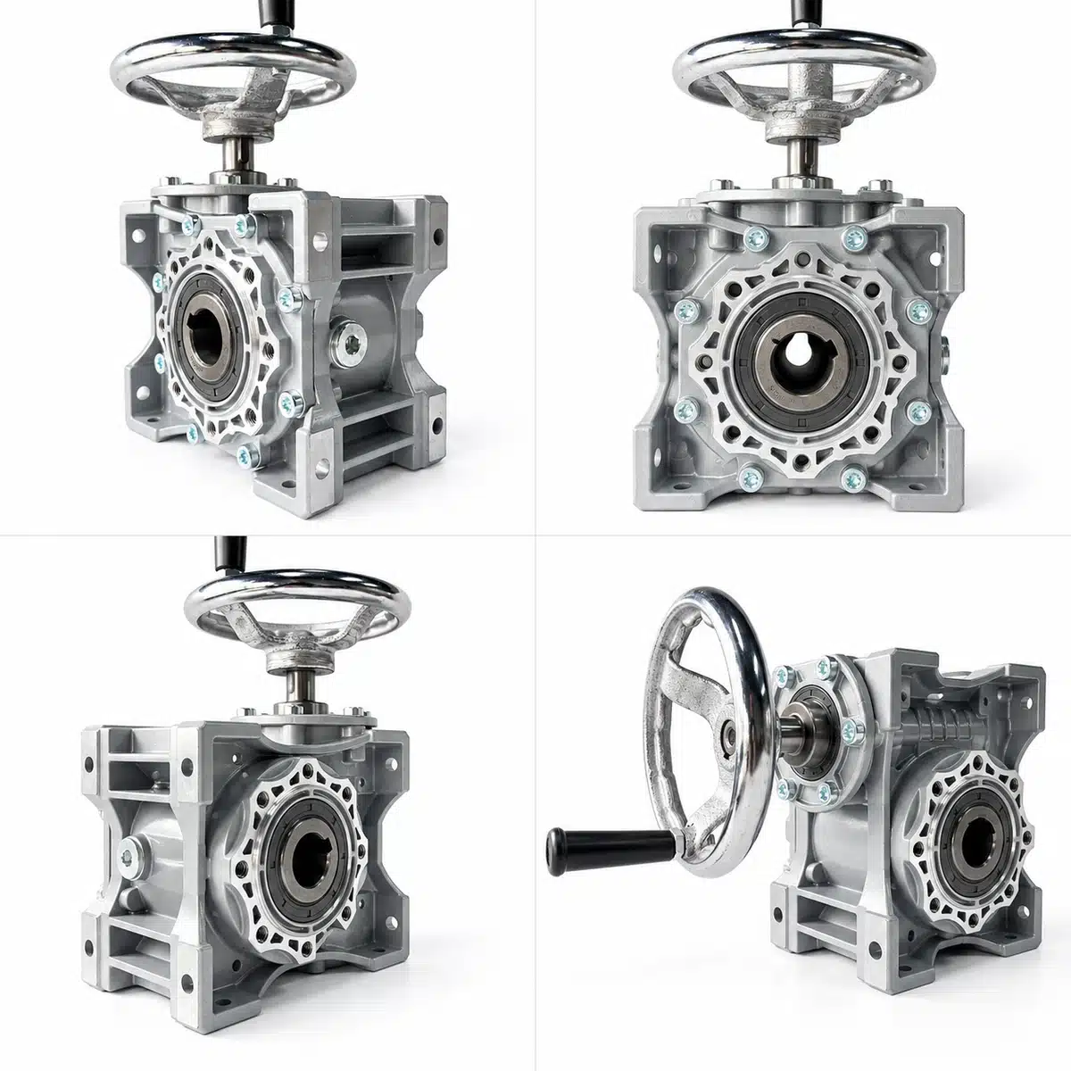
An NMRV worm gear reducer is a compact, right-angle industrial gearbox designed to reduce motor speed and transmit torque through a worm-and-wheel gear mechanism. Its input and output shaft axes are arranged at approximately 90 degrees, making it suitable for machinery where space-efficient power transmission is required.
NMRV worm gear reducers are widely used in packaging machinery, conveyor systems, food processing equipment, material handling systems, and industrial automation.
For OEM machinery manufacturers and industrial engineers, understanding the operating principle, internal construction, and limitations of an NMRV gearbox is essential when evaluating its suitability for a particular drive application.
How Does an NMRV Worm Gear Reducer Work?
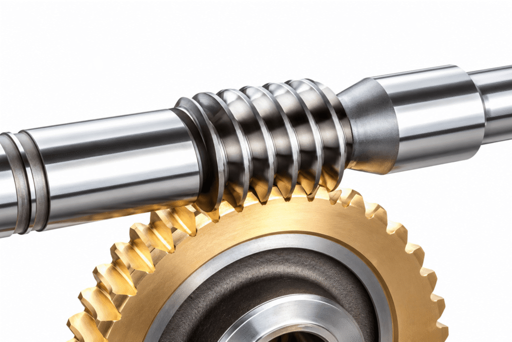
An NMRV worm gearbox transmits rotational power through two primary components: a worm shaft and a worm wheel.
The worm shaft is the driving component. Its screw-shaped thread engages the teeth of the worm wheel, transferring rotational motion to the output assembly.
As the motor rotates the worm, the worm wheel turns at a reduced speed determined by the gear ratio.
The transmission process involves four stages:
- Power input: An electric motor drives the worm shaft.
- Gear engagement: The worm thread meshes with the worm wheel teeth.
- Speed reduction: The gear geometry determines the relationship between input and output rotational speeds.
- Power output: The worm wheel transmits reduced-speed rotation through the gearbox output.
Unlike conventional inline gearboxes, the NMRV design changes the direction of power transmission while reducing rotational speed.
How Is the Worm Gear Ratio Calculated?
The nominal transmission ratio of a conventional worm gear pair is determined by:
Gear Ratio = Number of Worm Wheel Teeth ÷ Number of Worm Starts
For example, a single-start worm engaging a 40-tooth worm wheel produces a nominal reduction ratio of 40:1.
At an input speed of 1,400 RPM:
Output Speed = 1,400 ÷ 40 = 35 RPM
This calculation illustrates the operating principle. Actual output speed depends on the input motor speed and the gearbox’s nominal reduction ratio.
Standard KB NMRV worm gear reducers are available with nominal single-stage ratios including 7.5:1, 10:1, 15:1, 20:1, 25:1, 30:1, 40:1, 50:1, 60:1, 80:1, and 100:1, depending on gearbox size and configuration.
Main Components of an NMRV Worm Gear Reducer
An industrial NMRV reducer consists of precision-manufactured transmission components assembled within a rigid gearbox housing.
1. Hardened Steel Worm Shaft
The worm shaft transmits rotational power from the motor to the worm wheel.
KB NMRV worm shafts are manufactured from 20Cr alloy steel, with carburizing and quenching treatment to improve tooth surface hardness and wear resistance.
Key manufacturing characteristics include:
- Worm material: 20Cr alloy steel
- Tooth surface hardness: 56–62 HRC
- Carburized layer thickness after precision grinding: 0.3–0.5 mm
These properties support durability under the sliding-contact conditions characteristic of worm gear transmissions.
2. Wear-Resistant Bronze Worm Wheel
The worm wheel receives motion from the hardened steel worm and transfers torque to the output assembly.
KB NMRV reducers use a wear-resistant tin bronze alloy worm wheel, providing a material pairing suitable for industrial worm gear meshing.
The combination of hardened steel and bronze helps manage sliding contact and wear when the transmission is correctly lubricated and operated within its rated capacity.
3. Aluminum Alloy or Cast Iron Housing
The gearbox housing maintains the alignment of the transmission components, supports bearings, and contains the lubricant.
KB NMRV gear reducers use different housing materials according to frame size:
| NMRV Frame Size | Housing Material |
|---|---|
| NMRV025–NMRV105 | Die-cast aluminum alloy |
| NMRV110–NMRV150 | Cast iron |
Aluminum alloy housings provide a lightweight and compact construction for smaller frame sizes.
Cast iron housings are used for larger frame sizes where a more substantial housing structure is required.
The thermal performance of either housing type depends on gearbox dimensions, operating load, mounting position, airflow, and ambient conditions.
4. Bearings and Shaft Seals
Bearings support the rotating components and help maintain accurate shaft positioning during operation.
Shaft seals retain lubricant and limit the entry of contaminants.
Bearing condition, alignment, sealing integrity, and correct installation all contribute to gearbox reliability.
5. Lubrication System
Worm gearing involves considerable sliding contact between mating tooth surfaces.
Proper lubrication is essential for:
- Reducing friction and wear
- Controlling operating temperature
- Protecting the gear tooth surfaces
- Supporting reliable bearing operation
- Extending the service life of transmission components
Lubricant selection and filling quantity must follow the requirements for the specific gearbox configuration and mounting position.
Why Can an NMRV Gearbox Achieve a High Reduction Ratio?
A key characteristic of worm gearing is its ability to provide substantial speed reduction through a single worm-and-wheel gear pair.
The reduction ratio is determined by the number of worm starts and worm wheel teeth.
This allows an NMRV gearbox to achieve relatively high reduction ratios without requiring multiple conventional gear stages.
Combined with its right-angle configuration, this makes worm gearing useful where installation space is limited.
However, a higher reduction ratio does not automatically increase the gearbox’s permissible mechanical load.
Rated output torque, bearing loads, operating speed, and thermal capacity must still be considered.
How Does an NMRV Worm Gear Reducer Increase Output Torque?
When a gearbox reduces rotational speed, the output torque generally increases, subject to transmission efficiency and mechanical losses.
The relationship between input power, output speed, and output torque can be expressed as:
M₂ = (9550 × P₁ × η) ÷ n₂
Where:
- M₂: Output torque (Nm)
- P₁: Input power (kW)
- η: Transmission efficiency
- n₂: Output rotational speed (RPM)
This equation describes the relationship between power, speed, efficiency, and torque.
It should not be interpreted as the maximum permissible torque of a particular gearbox.
The actual rated output torque depends on the gearbox frame size, gear geometry, materials, bearings, and operating conditions.
What Are the Advantages of NMRV Worm Gear Reducers?
Compact Right-Angle Design
The 90-degree transmission arrangement allows the motor and driven equipment to be positioned on perpendicular axes.
This can simplify mechanical layouts in compact industrial machinery.
High Single-Stage Reduction Ratios
Worm gearing can provide substantial speed reduction within a single gear mesh, reducing the need for additional reduction stages in certain applications.
Smooth Mechanical Transmission
The continuous engagement between the worm and worm wheel can provide smooth operation and relatively low noise when the gearbox is correctly manufactured, lubricated, and installed.
Actual noise and vibration depend on operating speed, load, manufacturing accuracy, bearing condition, and mounting arrangements.
Flexible Input and Output Arrangements
Depending on the frame size and configuration, NMRV reducers can be supplied with motor-flange input, solid input shaft, hollow output bore, single output shaft, double output shaft, and output flange arrangements.
These configurations support integration into different industrial machine designs.
What Are the Limitations of NMRV Worm Gear Reducers?
Understanding the limitations of worm gearing is important for reliable equipment design.
1. Sliding Friction and Transmission Losses
Worm gearing generally involves a higher proportion of sliding contact than some other industrial gear arrangements.
This sliding action creates friction losses and reduces the amount of input power available at the output.
Actual transmission efficiency depends on gear ratio, geometry, operating speed, load, lubrication, and temperature.
2. Heat Generation During Operation
Frictional losses in the gear mesh, bearings, and seals are converted into heat.
For continuous-duty applications, the gearbox must be able to dissipate this heat under the expected operating conditions.
Thermal suitability should be considered alongside mechanical torque capacity.
3. Self-Locking Is Not Guaranteed
Some worm gear arrangements can resist reverse driving under specific operating conditions.
However, not all NMRV worm gear reducers are self-locking.
Back-driving behavior depends on gear geometry, friction, lubrication, temperature, wear, vibration, and external loading.
An NMRV gearbox must not be relied upon as the sole holding or braking device in lifting equipment, personnel-carrying systems, or other safety-critical applications.
Appropriate independently rated braking and protective systems must be used.
Typical Industrial Applications of NMRV Worm Gear Reducers
NMRV worm gearboxes are used in machinery that requires reduced output speed and right-angle power transmission.
Packaging Machinery
NMRV reducers can drive selected conveyors, product transfer mechanisms, and auxiliary machine assemblies in packaging production lines.
Conveyor Systems
They can transmit motor power to low-speed conveyor drives where the required output torque, radial loading, and duty cycle are compatible with the gearbox ratings.
Food Processing Equipment
NMRV gearboxes are used in appropriately specified conveying, mixing, and packaging equipment.
Environmental protection, washdown conditions, and lubricant requirements must be considered when selecting a gearbox for food processing applications.
Industrial Automation
Compact right-angle reducers can be used in material handling systems, rotary mechanisms, and auxiliary automated machinery.
Mixing and Material Handling Equipment
NMRV reducers can provide reduced-speed drive power for selected mixers, agitators, and material handling mechanisms when the mechanical and thermal requirements are satisfied.
Frequently Asked Questions
What is the main function of an NMRV worm gear reducer?
An NMRV worm gear reducer reduces input rotational speed and transmits power through a right-angle worm-and-wheel gear mechanism.
What is the difference between a worm shaft and a worm wheel?
The worm shaft is the screw-shaped driving component, while the worm wheel is the toothed driven component that transfers rotation to the gearbox output.
What materials are used in KB NMRV worm gear reducers?
KB NMRV reducers use hardened 20Cr alloy steel worm shafts and wear-resistant tin bronze alloy worm wheels. Housing materials vary by frame size, with aluminum alloy used for smaller models and cast iron for larger models.
Is an NMRV gearbox a 90-degree gearbox?
Yes. A conventional NMRV worm gear reducer uses perpendicular input and output shaft axes.
Can an NMRV worm gearbox operate continuously?
An appropriately selected NMRV reducer can be used for continuous-duty operation when its mechanical and thermal limits are satisfied.
Are all NMRV worm gear reducers self-locking?
No. Self-locking behavior depends on the specific gear design and operating conditions. It must not be assumed without engineering verification.
Why does an NMRV gearbox generate heat?
Sliding friction between the worm and worm wheel, together with bearing and seal losses, generates heat during operation. Temperature depends on the gearbox configuration, transmitted load, speed, lubrication, and cooling conditions.
NMRV Gearbox Technical Specifications and Engineering Resources
Understanding the working principle of an NMRV reducer helps engineers evaluate its basic transmission characteristics.
For actual equipment integration, additional information is required, including motor speed, output torque, mounting arrangement, operating duty, and environmental conditions.
Explore the KB NMRV Worm Gear Reducer product range for available configurations and technical specifications.
For frame-size information and model-specific performance data, refer to the NMRV Worm Gear Reducer Complete Model Guide.
Need NMRV Gearbox Specifications for Your Equipment?
Explore KB NMRV gearbox configurations and technical specifications, or contact our team for application-specific recommendations and a quotation.
About KB Transmission Star
KB Transmission Star, a brand of Taizhou Ubuty Co., Ltd., supplies industrial gear reducers and geared motors for OEM machinery manufacturers, industrial distributors, and equipment builders.
Our product range includes NMRV worm gear reducers, helical gearboxes, helical-bevel gearboxes, helical-worm gearboxes, and helical-hypoid gear units.
For technical documentation or application-specific inquiries, contact betsy@wormgearreducer.com..