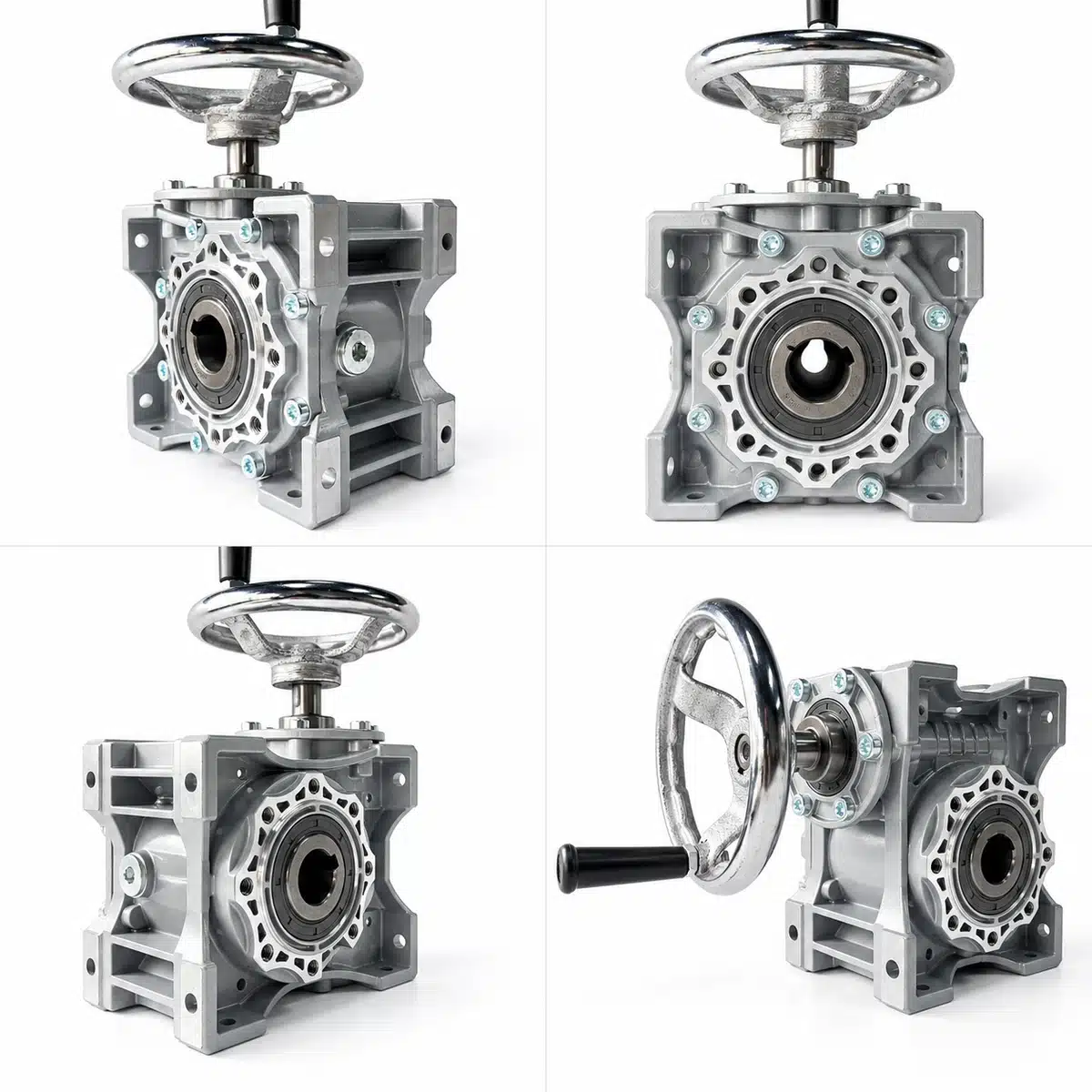
Proper industrial gearbox installation is essential for reliable power transmission, stable operation, and long equipment service life. Even a well-manufactured gearbox can experience premature bearing wear, excessive vibration, overheating, oil leakage, or coupling damage when installed incorrectly.
Whether you are installing an NMRV worm gear reducer, a helical gearbox, or another industrial gear unit, several installation principles are critical: correct mounting, accurate shaft alignment, suitable lubrication, secure fasteners, and controlled commissioning.
At KB Transmission Star, we support OEM equipment manufacturers, industrial distributors, and maintenance teams with gearbox selection and installation-related technical guidance.
This gearbox installation guide explains the key procedures, common mistakes, and inspection points that should be considered before putting a gearbox into service.
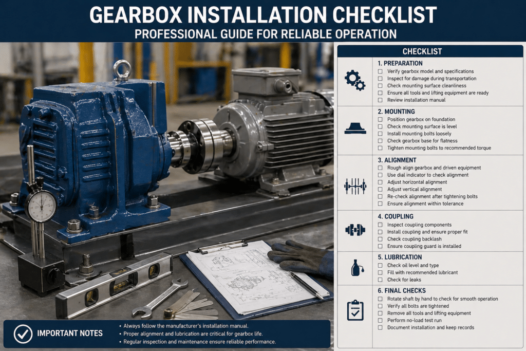
Quick Gearbox Installation Checklist
Before starting the installation, confirm the following essential requirements.
| Inspection Item | What to Check |
|---|---|
| Gearbox identification | Model, reduction ratio, motor interface, and mounting configuration |
| Visual condition | Housing, shafts, flanges, seals, and shipping damage |
| Mounting surface | Flatness, rigidity, cleanliness, and proper support |
| Shaft alignment | Coupling alignment and allowable misalignment |
| Drive components | Correct installation of couplings, keys, pulleys, and sprockets |
| Fasteners | Correct bolt specification and tightening torque |
| Lubrication | Oil type, fill level, and mounting-position requirements |
| Safety | Guards, electrical isolation, and safe access |
| Initial operation | Rotation direction, abnormal noise, vibration, and temperature |
| Documentation | Installation measurements and commissioning records |
This checklist provides a general starting point. Always follow the installation and operating instructions supplied with the specific gearbox.
1. Pre-Installation Inspection and Safety Checks
Before mounting an industrial gearbox, inspect the unit and confirm that it matches the equipment requirements.
Identifying problems before installation helps avoid unnecessary disassembly and commissioning delays.
Inspect the Gearbox for Shipping Damage
Examine the gearbox housing, input and output shafts, mounting flanges, and exposed seals.
Look for:
-
Housing cracks, dents, or visible deformation
-
Damaged shaft ends or keyways
-
Bent mounting flanges or damaged mounting feet
-
Missing plugs, accessories, or documentation
-
Signs of lubricant leakage
-
Damaged motor interfaces or fasteners
If shipping damage is suspected, do not place the gearbox into operation until its condition has been evaluated.
Check Shaft Rotation
Where permitted by the manufacturer’s instructions, carefully rotate the accessible shaft by hand with the drive safely isolated.
Check for unusual resistance, grinding, binding, or abnormal mechanical movement.
Some gearboxes may resist manual rotation because of their internal gearing, seals, or backdriving characteristics. Therefore, inability to rotate a shaft by hand does not automatically indicate internal damage.
If abnormal operation is suspected, consult the manufacturer before installation.
Verify the Gearbox Nameplate
Confirm that the delivered gearbox matches the required configuration.
Important information includes:
-
Gearbox model and frame size
-
Reduction ratio
-
Rated input speed
-
Motor interface
-
Output shaft configuration
-
Mounting arrangement
-
Lubrication specification
-
Applicable power and torque ratings
For replacement applications, also verify dimensional compatibility with the existing gearbox.
Prepare Shafts and Mounting Surfaces
Remove protective packaging and clean the relevant shaft and mounting surfaces according to the manufacturer’s instructions.
Use suitable cleaning materials that will not damage seals, coatings, or precision-machined surfaces.
Avoid scraping, grinding, or modifying precision mounting interfaces unless specifically required by an approved installation procedure.
2. Verify Gearbox Mounting Position and Lubrication
The installation position of a gearbox affects lubricant distribution, bearing lubrication, sealing, and thermal performance.
Before installation, confirm that the gearbox is configured for its intended operating orientation.
Why Mounting Position Matters
Different gearbox designs may require different lubrication arrangements depending on whether their shafts are installed horizontally or vertically.
An unsuitable mounting position can result in inadequate lubrication, excessive lubricant churning, leakage, or increased operating temperature.
For example, a gearbox prepared for horizontal operation may require a different lubricant quantity or additional accessories when installed in a vertical orientation.
The correct requirements depend on the gearbox design and manufacturer.
Common Mounting Arrangements
Industrial gearboxes may support:
-
Foot-mounted installation
-
Flange-mounted installation
-
Horizontal shaft arrangements
-
Vertical shaft arrangements
-
Hollow-shaft mounting
-
Shaft-mounted configurations
Mounting-position codes and their meanings are not necessarily identical across all gearbox families.
Always refer to the dimensional drawings and mounting-position diagrams for the specific model.
Check Lubricant Type and Fill Level
Before commissioning, confirm:
-
Whether the gearbox is supplied with lubricant
-
The required lubricant type and viscosity
-
The correct lubricant quantity
-
The specified oil-level checking procedure
-
The installation position for which the unit is configured
-
Whether a breather, vent, or additional sealing arrangement is required
Some compact gearboxes are supplied with long-life synthetic lubricant, while other industrial units require filling before operation.
Do not assume that all gearboxes require the same oil quantity or oil-change interval.
Changing the Mounting Position
If the installation orientation differs from the original specification, contact the gearbox manufacturer or consult the applicable installation manual.
Changing orientation may affect lubricant quantity, bearing lubrication, sealing, and thermal ratings.
Do not simply add or drain oil based on a general percentage adjustment.
3. Prepare the Foundation and Mounting Surface
A gearbox requires a stable mounting structure to maintain alignment and transmit mechanical loads safely.
Even accurate initial shaft alignment can deteriorate if the mounting base moves or deforms during operation.
Inspect the Mounting Surface
The mounting surface should be:
-
Clean and free from debris
-
Sufficiently rigid for the transmitted loads
-
Properly supported
-
Flat within the specified installation tolerance
-
Free from excessive distortion or damage
Mounting flatness requirements depend on the gearbox design, base dimensions, and manufacturer’s specifications.
Do not apply a single flatness tolerance to every gearbox model.
Check for Soft Foot
Soft foot occurs when one or more mounting feet do not contact the supporting surface correctly.
Tightening the mounting bolts can then introduce distortion or unwanted mechanical stress.
A typical soft-foot inspection involves checking the mounting contact points and identifying gaps or movement as individual fasteners are loosened under controlled conditions.
Where necessary, use suitable precision shims to correct the support.
After adjustment, verify the mounting condition and shaft alignment again.
Verify Foundation Rigidity
The foundation must withstand the static and dynamic loads generated during operation.
Consider:
-
Gearbox and motor weight
-
Starting and stopping loads
-
Torque reaction
-
Vibration
-
External shaft loads
-
Connected machinery movement
For heavy-duty applications, the mounting structure should be evaluated as part of the overall machine design.
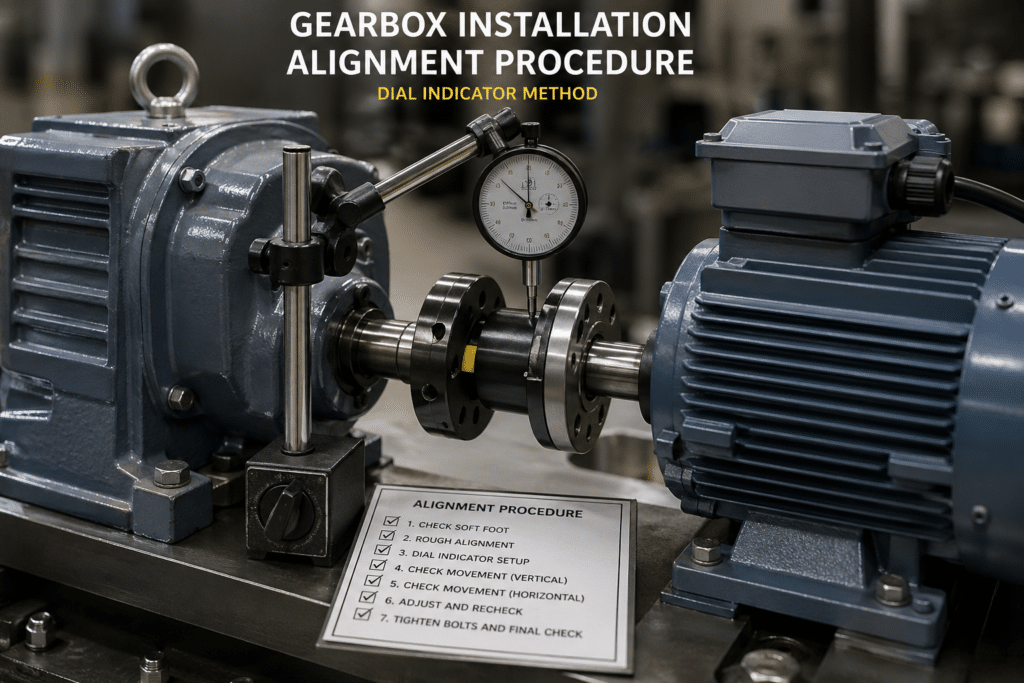
4. Gearbox Shaft Alignment Procedure
Accurate shaft alignment is one of the most important aspects of industrial gearbox installation.
Misalignment can increase bearing loads, coupling wear, vibration, and seal deterioration.
The required alignment accuracy depends on the coupling type, shaft speed, equipment configuration, and manufacturer’s recommendations.
Types of Shaft Misalignment
Parallel Misalignment
Parallel misalignment occurs when two shaft centerlines are parallel but offset from one another.
It can introduce additional forces into couplings, bearings, and connected machinery.
Angular Misalignment
Angular misalignment occurs when the shaft centerlines are not parallel.
This condition can create uneven coupling loading and additional mechanical stress.
Combined Misalignment
Many installations involve both parallel and angular misalignment.
Both conditions should be evaluated during alignment.
Recommended Alignment Tools
Common alignment methods include:
| Alignment Method | Typical Application | Considerations |
|---|---|---|
| Straightedge and feeler gauge | Preliminary alignment | Limited measurement accuracy |
| Dial indicator | Precision mechanical alignment | Requires suitable setup and interpretation |
| Laser alignment system | Industrial shaft alignment | Provides detailed alignment measurements and adjustment guidance |
The appropriate method depends on the equipment and required alignment accuracy.
Step-by-Step Shaft Alignment
Step 1: Position the Equipment
Install the gearbox and connected motor or driven equipment in their intended positions.
Confirm that the mounting surfaces are properly supported.
Step 2: Inspect the Coupling
Check the coupling type, dimensions, condition, and installation requirements.
Verify the specified axial spacing between coupling components.
Step 3: Measure Alignment
Use a suitable alignment instrument to measure parallel and angular misalignment.
Follow the measurement procedure specified for the selected instrument and coupling arrangement.
Step 4: Correct the Alignment
Adjust the motor or gearbox position as necessary.
Use suitable shims to correct vertical alignment and controlled lateral movement to correct horizontal alignment.
Step 5: Tighten Mounting Fasteners
Secure the equipment using the specified fastener tightening procedure.
Step 6: Recheck Alignment
Final tightening can change equipment position.
Repeat the alignment measurements and confirm that the final results satisfy the applicable requirements.
Important Alignment Considerations
Alignment limits should be obtained from the coupling or equipment manufacturer.
The final alignment should also account for thermal growth, operating loads, and other relevant machine conditions.
For critical applications, record the alignment readings as part of the commissioning documentation.
5. Install Couplings, Keys, and Drive Components
Incorrect installation of shaft-mounted components can damage bearings, shafts, keys, and seals.
Components should be installed using methods appropriate for their fit, material, and mechanical design.
Avoid Impact Loading
Do not use uncontrolled hammer blows to force couplings, pulleys, or sprockets onto gearbox shafts.
Impact forces may be transmitted through the shaft and damage internal bearings or retaining components.
Use the Correct Installation Method
Depending on the component design, approved installation methods may include:
-
Mechanical draw-up tools
-
Suitable mounting fixtures
-
Controlled hydraulic installation
-
Manufacturer-approved thermal fitting procedures
The correct method depends on the specified shaft and hub fit.
Do not apply heat to a component unless its manufacturer permits thermal installation and provides suitable temperature limits.
Check Keys and Keyways
Before installation, inspect the key and keyway for damage, burrs, or contamination.
Confirm that the key dimensions and fit match the applicable shaft and hub specifications.
Incorrect key fit can cause assembly problems, fretting, or transmission damage.
Verify External Shaft Loads
When installing pulleys, sprockets, or gears, consider the additional radial and axial loads applied to the gearbox output shaft.
These loads must remain within the permissible limits for the selected gearbox configuration.
For applications with significant belt or chain loading, the external load position should also be considered.
6. Mounting Bolts and Fastener Requirements
Mounting fasteners must maintain the gearbox position and withstand the loads generated during operation.
Incorrect fastener selection or tightening can cause loosening, mounting distortion, or thread damage.
Select Suitable Fasteners
Confirm the required:
-
Bolt diameter and thread specification
-
Fastener property class
-
Engagement length
-
Washer or locking arrangement
-
Tightening torque
-
Surface and thread condition
Fastener requirements vary according to gearbox size, mounting material, connection design, and loading.
Follow the Specified Tightening Torque
Do not apply a universal bolt torque table without considering the connection design.
Tightening torque depends on factors such as fastener grade, lubrication, thread condition, friction, and joint requirements.
Use the torque specifications supplied by the gearbox or equipment manufacturer.
Tighten Fasteners Progressively
For mounting arrangements with multiple fasteners, progressive tightening can help distribute clamping forces more evenly.
Where applicable, follow the specified tightening sequence and complete a final verification after the equipment has been secured.
Recheck Alignment
After tightening, confirm that the gearbox remains correctly positioned.
Where required, repeat shaft alignment and mounting measurements.
7. Pre-Start Inspection and Gearbox Commissioning
Commissioning verifies that the installed gearbox operates correctly before normal production begins.
The procedure should follow the manufacturer’s instructions and the safety requirements of the complete machine.
Pre-Start Inspection
Before energizing the equipment, confirm:
-
Mounting fasteners are secured
-
Couplings and drive components are installed correctly
-
Protective guards are fitted
-
Lubrication requirements are satisfied
-
Electrical connections are correct
-
The driven machine is ready for operation
-
Tools and loose objects have been removed
-
Required safety systems are operational
Verify Rotation Direction
Where the equipment design permits, check the output rotation direction using a controlled startup procedure.
An incorrect rotation direction can affect the operation of conveyors, pumps, mixers, and other driven equipment.
Follow the electrical and mechanical safety procedures applicable to the machine.
Conduct Initial Operation
During initial operation, monitor the gearbox for:
-
Unusual noise
-
Excessive vibration
-
Oil leakage
-
Abnormal temperature rise
-
Unexpected movement
-
Irregular operation of connected equipment
If abnormal behavior occurs, stop the equipment safely and investigate the cause.
Monitor Operating Temperature
Gearbox temperature depends on the gear design, transmitted load, operating speed, lubricant, ambient temperature, and ventilation.
Worm gearboxes and helical gearboxes may exhibit different thermal characteristics.
A single temperature threshold should not be used to judge every gearbox.
Compare operating conditions with the permissible temperature limits and thermal ratings supplied for the specific model.
Record Commissioning Results
For industrial applications, maintain records of:
-
Gearbox model and serial number
-
Installation position
-
Lubricant specification
-
Alignment measurements
-
Fastener verification
-
Operating speed
-
Initial vibration observations
-
Temperature observations
-
Commissioning date
These records can support future maintenance and troubleshooting.
8. Common Gearbox Installation Mistakes
Many gearbox operating problems can be traced to installation conditions.
The following table summarizes common installation-related issues and appropriate corrective actions.
| Installation Problem | Potential Consequence | Recommended Action |
|---|---|---|
| Incorrect mounting position | Inadequate lubrication or leakage | Verify the approved installation orientation |
| Shaft misalignment | Vibration, coupling wear, bearing loading | Measure and correct alignment |
| Soft foot | Mounting distortion and vibration | Inspect mounting contact and correct support |
| Incorrect lubricant | Increased wear or overheating | Follow the specified lubricant requirements |
| Incorrect oil level | Lubrication problems or excessive churning | Verify the required oil level |
| Excessive external shaft load | Premature bearing wear | Check radial and axial load limits |
| Improper coupling installation | Shaft or bearing damage | Use approved assembly methods |
| Incorrect bolt tightening | Loosening or mounting distortion | Apply the specified tightening procedure |
| Inadequate ventilation | Increased operating temperature | Maintain suitable airflow |
| Incorrect rotation direction | Improper driven-machine operation | Verify rotation before normal production |
Installation errors are not the only causes of gearbox problems. Incorrect sizing, overload, contamination, inadequate maintenance, and unsuitable operating conditions can also contribute to premature failure.
For diagnosing problems after equipment has entered service, read our Worm Gearbox Troubleshooting Guide.
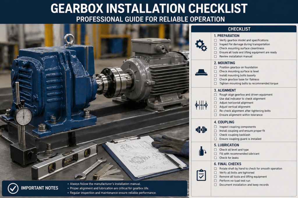
9. Printable Gearbox Installation Checklist
Use the following checklist before releasing an industrial gearbox for normal operation.
Pre-Installation
-
Gearbox model and reduction ratio verified
-
Motor and output interfaces confirmed
-
Housing, shafts, and mounting surfaces inspected
-
Shipping damage checked
-
Required documentation available
Mounting
-
Installation position confirmed
-
Foundation and mounting surfaces inspected
-
Soft foot checked and corrected where necessary
-
Mounting fasteners selected correctly
-
Fasteners tightened according to specifications
Shaft Alignment
-
Coupling inspected
-
Parallel alignment checked
-
Angular alignment checked
-
Alignment corrected where necessary
-
Final alignment verified after tightening
Drive Components
-
Keys and keyways inspected
-
Couplings installed using approved methods
-
External shaft loads checked
-
Protective guards installed
Lubrication
-
Lubricant type verified
-
Oil level checked according to the installation position
-
Required plugs and vents configured correctly
-
No visible leakage
Commissioning
-
Electrical and mechanical safety checks completed
-
Rotation direction verified
-
Initial operating condition monitored
-
Noise and vibration checked
-
Operating temperature observed
-
Commissioning results documented
This checklist should be used together with the manufacturer’s installation manual and the safety procedures for the complete machine.
10. Frequently Asked Questions About Gearbox Installation
What should be checked before installing a gearbox?
Before installation, verify the gearbox model, reduction ratio, motor interface, mounting position, lubrication requirements, and overall condition.
The foundation, mounting surfaces, couplings, and required fasteners should also be inspected.
How important is shaft alignment during gearbox installation?
Shaft alignment is essential for reducing unwanted coupling forces, vibration, and bearing loading.
The required alignment accuracy depends on the coupling design, shaft speed, and equipment specifications.
Can a gearbox be installed in any mounting position?
Not necessarily.
Available mounting positions depend on the gearbox design and lubrication arrangement.
Some configurations require different oil quantities, seals, or accessories.
How do I know the correct gearbox oil level?
Use the oil-level procedure and lubricant specifications provided for the particular gearbox model and mounting position.
Do not assume that the same oil quantity applies to every installation orientation.
Should a new gearbox run without load before normal operation?
Some gearboxes require a controlled initial operating or run-in procedure.
The appropriate commissioning sequence depends on the gearbox design and manufacturer.
Follow the supplied instructions rather than applying a universal run-in duration.
What causes excessive gearbox vibration after installation?
Potential causes include shaft misalignment, soft foot, loose fasteners, unbalanced drive components, excessive external loads, or internal mechanical problems.
A systematic inspection is necessary to identify the cause.
Can I replace an existing gearbox with another manufacturer’s model?
Replacement is possible when the mechanical, dimensional, and performance requirements are satisfied.
Check the mounting dimensions, motor interface, output shaft, reduction ratio, torque capacity, and operating conditions before replacement.
11. Gearbox Installation Support for OEM Manufacturers
KB Transmission Star, supported by Taizhou Ubuty Co., Ltd., supplies industrial gear reducers and geared motors for OEM equipment manufacturers, industrial distributors, and machinery applications.
Our product range includes:
For new machinery projects or gearbox replacement applications, our team can assist with product selection, motor compatibility, dimensional requirements, and suitable mounting configurations.
Need Technical Support for Gearbox Installation or Replacement?
Tell us about your application, gearbox model, motor power, reduction ratio, mounting arrangement, and operating requirements.
Our team can review your information and help identify a suitable gearbox configuration for your project.
Explore Our Industrial Gearbox Product Range
Conclusion
Correct gearbox installation requires careful attention to mounting conditions, shaft alignment, lubrication, drive components, fastener requirements, and commissioning procedures.
A systematic installation process can help reduce avoidable mechanical problems and improve equipment reliability.
For the best results, always use the installation instructions and technical specifications supplied with the selected gearbox.
Whether you are installing an NMRV worm gear reducer or an industrial helical gearbox, proper installation is an important part of achieving reliable power transmission performance.
Need Technical Support for Gearbox Installation or Replacement?
Tell us about your application, gearbox model, motor power, reduction ratio, mounting arrangement, and operating requirements. Our team can help identify a suitable gearbox configuration for your project.