How to Select the Right Worm Gear Reducer: A Definitive B2B Selection Guide
For industrial engineers, procurement managers, and OEM designers, the efficiency of a power transmission system hinges on one critical decision: selecting the correct gearbox. A mismatched unit leads to premature failure, excessive heat, and costly downtime.
As a professional worm gearbox manufacturer, we understand that the selection process can be daunting. This comprehensive worm gearbox selection guide is designed to walk you through the technical nuances of worm gear reducer sizing, ensuring you choose a unit that delivers peak performance for your specific industrial application.
Step 1 – Determine Required Output Torque
The most fundamental rule in worm gear reducer sizing is that the gearbox must be rated to handle the load it will drive. Unlike electric motors, which are categorized by power (HP/kW), gearboxes are primarily rated by output torque (M2).
1.1 Calculate Nominal Torque
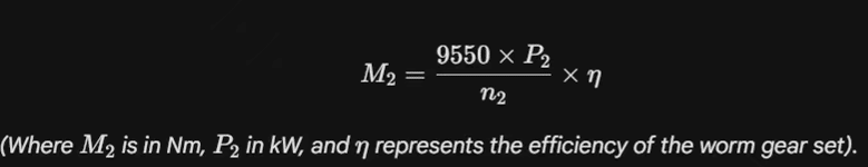
To find the required torque, you must know the speed (n2) and the power (P2) required by your driven machine. The basic formula is:
1.2 Apply the Service Factor (fs)
In B2B industrial applications, a gearbox rarely runs under “perfect” conditions. You must adjust your required torque based on the nature of the application:
- Uniform Loads (e.g., small fans, light conveyors): fs≈ 1.0
- Moderate Shock Loads (e.g., heavy conveyors, stirrers): fs≈ 1.25 – 1.5
- Heavy Shock Loads (e.g., crushers, reciprocating pumps): fs≈ 1.75 – 2.0
Manufacturer’s Tip: Always select a gearbox with a design torque (M2n) greater than your calculated torque multiplied by the service factor (M2 × fs).
Step 2 – Determine Speed Reduction Ratio
The worm gear mechanism is prized for its ability to achieve significant speed reduction in a single stage. The reduction ratio (i) determines the relationship between the input speed (n1) and the required output speed (n2).
2.1 The Calculation
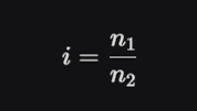
For example, if you are using a standard 4-pole motor (approx. 1400 RPM) and you need an output speed of 28 RPM, your ratio is 1400 / 28 = 50.
2.2 Single Stage vs. Double Stage
- Single Stage (5:1 to 100:1): Most common for standard NMRV series.
- Double Stage (Up to 5000:1): By combining two worm gearboxes (e.g., NMRV 040 + NMRV 090), you can achieve incredibly slow speeds for specialized machinery like heavy-duty solar trackers or rotating ovens.
Note on Self-Locking: If your application requires the load to stay in place when the motor stops (e.g., a vertical hoist), look for ratios above 40:1. However, never rely on a worm gearbox as the sole safety brake; always use a braked motor for critical safety.
Step 3 – Choose Gearbox Size
Once you have your torque and ratio, it is time to choose the physical frame size. In the global industrial market, the NMRV series has established a standard for interchangeable sizing based on the distance between the center of the worm and the center of the wheel (in mm).
3.1 Common NMRV Sizes
- Small (NMRV 025 – 050): Ideal for packaging machines, small food mixers, and medical equipment.
- Medium (NMRV 063 – 090): The “workhorses” of the conveyor and logistics industry.
- Large (NMRV 110 – 150): Heavy-duty units for mining, large agitators, and construction machinery.
3.2 Thermal Capacity
A critical part of this worm gearbox selection guide is checking the thermal limit. Because worm gears generate heat through sliding friction, the housing must be large enough to dissipate that heat. If you select a gearbox that is technically strong enough but physically too small for the duty cycle, the oil will overheat, leading to seal failure.
Step 4 – Select Mounting Position
Because the worm gear reducer is a right-angle drive, its mounting position drastically affects lubrication and longevity. In our factory, we categorize these as B3, B8, V5, V6, etc.
4.1 Lubrication Considerations
- Horizontal Mounting (B3): The safest and most common. Gears are partially submerged in oil.
- Vertical Mounting (V5/V6): Requires special attention. In a vertical orientation, the top bearing may sit above the oil level.
- The Solution: For vertical mounts, we often recommend “Life-lubricated” synthetic oil or the addition of an expansion tank to ensure the upper bearings remain lubricated.
B2B Buyer Checklist: Always specify your mounting orientation during the RFQ (Request for Quote) phase so the factory can set the correct oil level and breather plug position.
Step 5 – Check Motor Compatibility
Finally, ensure the gearbox can be physically mated to your power source. Standard worm gear reducer sizing follows IEC or NEMA flange standards.
5.1 Input Flange Dimensions
You must match the motor’s flange size (e.g., PAM 80B5 or 90B14) to the gearbox input.
- B5 Flange: Large flange, diameter exceeds the gearbox width.
- B14 Flange: Small flange, stays within the gearbox profile.
5.2 Shaft Compatibility
Verify that the motor shaft diameter matches the gearbox input bore (e.g., 19mm, 24mm, 28mm). We provide various sleeve bush options to accommodate different motor shaft sizes, ensuring a plug-and-play experience for your assembly team.
Conclusion: Partnering with a Specialist Factory
Selecting the right unit is the difference between a machine that runs for years and one that fails in months. This worm gearbox selection guide provides the technical foundation, but real-world variables—like ambient temperature, corrosive environments, or frequent stop-starts—often require expert consultation.
As an established manufacturer, we don’t just provide a catalog; we provide a partnership. We specialize in worm gear reducer sizing for global B2B clients, offering NMRV-equivalent units with 1:1 interchangeability and premium technical support.
Ready to finalize your selection?
Contact our engineering team today for a free technical audit of your drive requirements, or Request our 2D/3D CAD library to begin integrating our reducers into your designs.