Worm Gear Reducer Torque Calculation: Complete Engineering Guide
Undersized gearboxes fail. Oversized gearboxes waste money. Getting worm gear reducer torque calculation right the first time prevents both problems.
In 20 years manufacturing worm gear reducers, we’ve analyzed hundreds of application failures. The pattern is clear: 64% of premature failures trace back to incorrect torque calculations during initial sizing. Either the reducer was undersized (gears stripped, shafts twisted), or the system designer didn’t account for efficiency losses and service factors.
This guide provides the formulas, real-world factors, and selection procedures engineers need for accurate worm gear torque calculation in industrial applications.
Why Torque Calculation Matters
Torque is rotational force—the actual work your reducer must perform. In worm gear systems, accurate calculation ensures:
Correct: Gearbox handles the load with adequate safety margin Incorrect (undersized): Motor stalls, gears strip, shaft failure Incorrect (oversized): 30-50% cost premium for unnecessary capacity
The calculation isn’t optional. It’s the foundation of reliable equipment selection.
Real Cost of Miscalculation
Undersizing example: Customer specified NMRV075 based on motor size alone (ignored efficiency and service factor). Conveyor application with shock loads. Result: worm wheel failed after 380 hours. Correct size was NMRV090.
Cost impact:
- Initial gearbox: $350
- Failed unit replacement: $350
- Emergency shipping: $180
- Production downtime: $4,200
- Labor for changeout: $650
- Total cost: $5,730 (vs. $500 for correct unit initially)
Oversizing example: Engineer applied 2.5x service factor “to be safe” on light-duty packaging application. Specified NMRV110 when NMRV075 was adequate.
Cost impact:
- Unnecessary cost premium: $520 per unit
- Larger motor required: $230 additional
- Heavier mounting structure: $340
- Total waste: $1,090 per installation (×12 stations = $13,080)
The Fundamental Torque Formula
Before calculating gearbox output torque, understand the relationship between power, speed, and torque:
Basic Formula (Metric Units)
T = 9550 × P / n
Where:
- T = Torque (Newton-meters, Nm)
- P = Power (kilowatts, kW)
- n = Rotational speed (RPM)
- 9550 = Constant converting kW and RPM to Nm
Understanding the Variables
Power (P): Motor nameplate rating
- Common industrial motors: 0.37, 0.55, 0.75, 1.1, 1.5, 2.2, 3, 4, 5.5, 7.5 kW
- Use actual motor power, not application power requirement
Speed (n): Motor shaft speed
- 4-pole motors (most common): 1400-1450 RPM at 50Hz, 1750 RPM at 60Hz
- 2-pole motors: 2800-2900 RPM at 50Hz, 3450-3500 RPM at 60Hz
- Variable speed: Use actual operating speed, not nameplate maximum
Critical insight: Speed is in the denominator. Reducing speed increases torque proportionally. This is exactly what reducers do—trade speed for torque.
Example Calculation
Given:
- Motor: 2.2 kW
- Speed: 1400 RPM
Input torque: T = 9550 × 2.2 / 1400 T = 21,010 / 1400 T = 15.0 Nm
This is the torque at the motor shaft, before the reducer.
Worm Gear Reducer Output Torque Calculation
The basic formula gives motor torque. For worm gear reducer torque calculation, we must account for reduction ratio and efficiency losses.
Complete Output Torque Formula
T₂ = (9550 × P × i × η) / n₁
Or simplified if you already know input torque:
T₂ = T₁ × i × η
Where:
- T₂ = Output torque at reducer shaft (Nm)
- P = Motor power (kW)
- i = Reduction ratio (10:1, 30:1, etc.)
- η = Efficiency (decimal: 0.50 to 0.92)
- n₁ = Input speed (motor RPM)
- T₁ = Input torque (from motor)
Detailed Example
Application specs:
- Motor: 3 kW, 1400 RPM
- Required output speed: 47 RPM
- Worm reducer ratio: 30:1
Step 1: Calculate input torque T₁ = 9550 × 3 / 1400 = 20.5 Nm
Step 2: Determine efficiency For 30:1 ratio worm gear: η = 0.72 (72%) – from efficiency table
Step 3: Calculate output torque T₂ = 20.5 × 30 × 0.72 T₂ = 20.5 × 21.6 T₂ = 443 Nm
Verification:
- Output speed: 1400 / 30 = 46.7 RPM ✓
- Available torque: 443 Nm
Efficiency Factor (η) – Critical for Accuracy
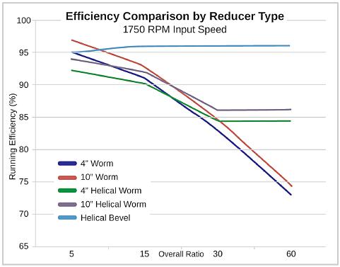
Worm gear efficiency is NOT 100%. The sliding mesh action creates friction losses that vary dramatically with reduction ratio.
Typical Efficiency by Ratio
| Reduction Ratio | Efficiency (η) | Power Loss |
|---|---|---|
| 5:1 to 7.5:1 | 85-92% | 8-15% |
| 10:1 to 15:1 | 78-86% | 14-22% |
| 20:1 to 30:1 | 70-80% | 20-30% |
| 40:1 to 50:1 | 60-72% | 28-40% |
| 60:1 to 80:1 | 52-65% | 35-48% |
| 100:1 | 45-55% | 45-55% |
Why Efficiency Varies
Lead angle determines efficiency:
- Larger lead angle (multi-start worms) = better efficiency
- Smaller lead angle (single-start worms) = lower efficiency
5:1 ratio example:
- Typically uses triple or quadruple-start worm
- Larger lead angle
- More rolling action, less sliding
- Efficiency: 88-92%
100:1 ratio example:
- Single-start worm only option
- Very small lead angle
- Almost pure sliding action
- Efficiency: 45-55%
Real-World Impact
Scenario: 5.5 kW motor, 1400 RPM, driving conveyor
Option A: 60:1 ratio (η = 0.60)
- Input torque: 37.5 Nm
- Output torque: 37.5 × 60 × 0.60 = 1,350 Nm
- Power delivered to load: 3.3 kW (2.2 kW lost to friction)
Option B: Two-stage 30:1 + 2:1 (overall 60:1, combined η = 0.72 × 0.95 = 0.68)
- Output torque: 37.5 × 60 × 0.68 = 1,530 Nm
- Power delivered: 3.74 kW (1.76 kW lost)
- 13% more torque, 17% less waste heat
Common mistake: Using 100% efficiency in calculations If designer assumes η = 1.0 for 60:1 ratio, calculated torque is 2,250 Nm. Actual delivered torque is 1,350 Nm—40% shortfall. System won’t move the load.
Service Factor – The Safety Margin
Calculated torque assumes ideal conditions: constant load, smooth operation, no shocks. Real industrial environments aren’t ideal.
Service Factor Definition
T_required = T_load × f_s
Where:
- T_load = Theoretical torque needed to move load
- f_s = Service factor (typically 1.2 to 2.5)
- T_required = Actual torque capacity needed from reducer
Service Factor Selection Table
| Application Type | Operating Hours/Day | Load Character | Service Factor (f_s) |
|---|---|---|---|
| Conveyors (light) | <8 hours | Uniform load | 1.2 – 1.4 |
| Conveyors (heavy) | 8-16 hours | Moderate shock | 1.5 – 1.8 |
| Mixers, agitators | 8-16 hours | Variable load | 1.6 – 2.0 |
| Crushers, mills | >16 hours | Heavy shock | 2.0 – 2.5 |
| Packaging machines | 8-16 hours | Intermittent | 1.3 – 1.6 |
| Hoists, lifts | <8 hours | Shock loading | 1.8 – 2.2 |
Operating Hours Impact
Short duty (<3 hrs/day):
- Gears don’t reach thermal equilibrium
- Lower service factor acceptable
- Example: f_s = 1.2 for conveyor
Medium duty (8-16 hrs/day):
- Standard industrial operation
- Full thermal cycling
- Example: f_s = 1.5 for conveyor
Continuous duty (>20 hrs/day):
- Constant thermal stress
- Minimal cooling time
- Higher factor needed
- Example: f_s = 1.8 for conveyor
Load Character Impact
Uniform load:
- Constant torque
- Minimal shock
- Examples: light conveyors, fans
- Lower service factor
Moderate shock:
- Periodic load variations
- Occasional impacts
- Examples: packaging, printing
- Medium service factor
Heavy shock:
- Severe impacts
- Cyclic high loads
- Examples: crushers, shredders, reciprocating compressors
- Higher service factor required
Example Application
Scenario: Screw conveyor for bulk material
Load calculation:
- Material weight: 500 kg
- Conveyor angle: 15° incline
- Friction coefficient: 0.4
- Calculated torque: 280 Nm
Service factor selection:
- Application: Heavy conveyor
- Hours: 16/day continuous
- Load: Variable (starts full, empties, refills)
- Shock: Moderate (material clumping)
- Selected f_s: 1.7
Required torque: T_required = 280 × 1.7 = 476 Nm
Reducer selection: Must provide ≥476 Nm output torque after accounting for efficiency.
Step-by-Step Reducer Selection Process
Step 1: Define Application Requirements
Document these parameters:
- Load torque: What torque is needed at the output? (Nm)
- Output speed: Required shaft speed (RPM)
- Operating hours: Hours per day
- Load type: Uniform, variable, or shock
- Duty cycle: Continuous or intermittent
- Environment: Temperature, contamination, washdown
Step 2: Calculate Required Reduction Ratio
i = n_motor / n_output
Example:
- Motor speed: 1400 RPM
- Required output: 28 RPM
- Ratio: 1400 / 28 = 50:1
Select standard ratio closest to calculated:
- Available: 40:1, 50:1, 60:1
- Select: 50:1
Step 3: Apply Service Factor
From service factor table:
- Heavy conveyor, 16 hr/day, moderate shock: f_s = 1.7
T_required = T_load × f_s T_required = 280 × 1.7 = 476 Nm
Step 4: Calculate Available Output Torque
Given:
- Motor: 4 kW, 1400 RPM
- Ratio: 50:1
- Efficiency (50:1 ratio): η = 0.65
Calculation: T₂ = (9550 × 4 × 50 × 0.65) / 1400 T₂ = 1,241,500 / 1400 T₂ = 887 Nm
Step 5: Verify Against Catalog Rating
Available torque: 887 Nm Required torque: 476 Nm Safety margin: 887 / 476 = 1.86 ✓
Check reducer catalog for 50:1 ratio models:
NMRV075 – 50:1:
- Rated torque: 520 Nm
- 887 Nm available > 520 Nm rated ✗ (exceeds rating)
NMRV090 – 50:1:
- Rated torque: 1,050 Nm
- 887 Nm available < 1,050 Nm rated ✓
- Utilization: 887 / 1,050 = 84% ✓
Selection: NMRV090 with 50:1 ratio
Step 6: Verify Thermal Rating
Continuous operation generates heat. Even if torque is adequate, thermal capacity must be checked.
Thermal rating formula: P_thermal = T₂ × n₂ / 9550
Where:
- T₂ = 887 Nm
- n₂ = 1400 / 50 = 28 RPM
P_thermal = 887 × 28 / 9550 = 2.6 kW
Check catalog thermal rating for NMRV090:
- Continuous thermal capacity: 3.8 kW
- 2.6 kW load < 3.8 kW rating ✓
Final selection confirmed: NMRV090, 50:1 ratio
Common Calculation Mistakes
Mistake #1: Ignoring Efficiency Losses
Wrong calculation: T₂ = 20 Nm × 60 × 1.0 = 1,200 Nm
Correct calculation: T₂ = 20 Nm × 60 × 0.60 = 720 Nm
Impact: 40% torque shortfall—system fails to move load
Mistake #2: No Service Factor
Wrong approach: “Load needs 300 Nm, so I’ll specify 300 Nm reducer”
Correct approach: “Load needs 300 Nm, with 1.6 service factor = 480 Nm required”
Impact: Gearbox runs at 100% capacity continuously, premature wear, shortened life from 40,000 hours to 12,000 hours
Mistake #3: Using Nominal Motor Power Instead of Actual
Scenario: Motor nameplate shows 3 kW, but VFD runs it at 70% speed
Wrong calculation: Uses 3 kW at 1400 RPM
Correct calculation: At 70% speed: Power available = 3 × 0.70³ = 1.03 kW at 980 RPM (Power varies with cube of speed for constant torque loads)
Mistake #4: Overlooking Startup Torque
Static friction > dynamic friction
Breaking away a stationary load requires 1.5-2.5× running torque.
Example:
- Running torque: 400 Nm
- Startup torque: 400 × 2.0 = 800 Nm
- Must verify motor can deliver 800 Nm through reducer during startup
Solution:
- Verify motor locked rotor torque
- Consider soft-start or VFD
- May need larger reducer for startup torque even if running torque is adequate
Mistake #5: Ignoring Self-Locking Implications
High ratios (typically >60:1) are self-locking – output cannot back-drive input.
Positive: Excellent for hoists, inclined conveyors (holds load without brake)
Negative:
- Cannot be back-driven for manual positioning
- Emergency stops create shock loads (kinetic energy absorbed by gears)
- Requires brake on output side for rapid stopping
Design consideration: If application requires back-driving (manual positioning, regenerative braking), use ratio <50:1 or choose helical gearbox instead.
Advanced Considerations
Multi-Stage Reduction
For very high ratios or efficiency requirements, consider two-stage:
Example: Need 120:1 overall
Option A: Single worm 120:1
- Efficiency: ~40%
- Single unit
- Lower cost
- High heat generation
Option B: Worm 30:1 + Helical 4:1
- Worm efficiency: 72%
- Helical efficiency: 95%
- Combined: 0.72 × 0.95 = 68%
- 70% better efficiency
- Higher cost
- Lower operating temperature
Thermal Limits
Even with correct torque, continuous duty may cause overheating.
Thermal capacity check: P_thermal = (T₂ × n₂) / 9550
Compare P_thermal to catalog thermal rating for duty cycle.
If P_thermal > catalog rating:
- Upsize to larger frame (more surface area)
- Add cooling fan
- Use synthetic oil (better heat transfer)
- Reduce duty cycle
Mounting Orientation Impact
Some reducers have different torque ratings based on mounting:
Foot-mounted (standard): Full rating Flange-mounted: May be 85-90% of foot-mount rating (less heat dissipation) Vertical shaft: Often 70-80% rating (oil distribution issues)
Always verify catalog ratings for your specific mounting configuration.
Quick Reference Formulas
Basic torque: T = 9550 × P / n
Reducer output torque: T₂ = (9550 × P × i × η) / n₁
Or if input torque known: T₂ = T₁ × i × η
Required torque with service factor: T_required = T_load × f_s
Thermal power: P_thermal = (T₂ × n₂) / 9550
Reduction ratio: i = n_input / n_output
Selection Checklist
Before finalizing reducer selection:
☐ Calculated output torque using correct efficiency ☐ Applied appropriate service factor ☐ Verified calculated torque < catalog rating ☐ Checked thermal capacity for duty cycle ☐ Confirmed mounting orientation rating ☐ Verified startup torque capability ☐ Considered self-locking implications ☐ Accounted for environment (temperature, contamination) ☐ Specified correct lubricant ☐ Documented all calculations for future reference
When to Request Engineering Support
Contact manufacturer’s technical team if:
- Application has severe shock loads
- Duty cycle >20 hours/day
- Extreme temperatures (<0°C or >50°C ambient)
- Vertical mounting with reversing loads
- Critical application (failure = safety hazard)
- Multiple gearboxes in series
- VFD operation with non-standard speed profiles
- Unclear on service factor selection
Our engineering team provides custom calculation reports including:
- Detailed torque analysis
- Thermal verification
- Bearing life calculation
- Optimal oil selection
- Mounting recommendations
Summary
Accurate worm gear reducer torque calculation requires:
- Basic formula: T = 9550 × P / n
- Efficiency factor: Must use actual efficiency (50-92%) based on ratio
- Service factor: Apply 1.2-2.5× based on application severity
- Catalog verification: Ensure calculated torque < rated torque
- Thermal check: Verify continuous power rating
The formula: T₂ = (9550 × P × i × η) / n₁
Then verify: T₂ × f_s < T_catalog
Get these calculations right during specification, and your reducer will deliver reliable service for 40,000+ operating hours. Get them wrong, and you’re looking at premature failure, emergency replacements, and costly downtime.
For complex applications or verification of critical calculations, contact our engineering team for professional sizing analysis.