Worm Gear Reducer for Conveyor Systems: Selection and Sizing Guide
Conveyor downtime costs vary significantly by industry: high-volume manufacturing facilities may lose $5,000-$25,000+ per hour, food processing operations $3,000-$15,000+ per hour, and distribution centers $8,000-$20,000+ per hour. The gearbox is often the single point of failure that stops entire production lines.
In our 20 years manufacturing worm gear reducers for conveyor systems, we’ve analyzed 1,200+ conveyor drive failures. The data is clear: 58% stem from incorrect gearbox selection, 23% from improper application, and only 19% from actual component wear. Most failures were preventable with proper sizing and specification.
This guide provides the engineering criteria, selection procedures, and application-specific considerations for specifying conveyor worm gear reducers that deliver reliable operation in material handling systems.
Why Worm Gear Reducers Are Widely Used in Conveyor Applications
Worm gear reducers are widely used in conveyor applications due to specific functional advantages that directly address conveyor drive requirements. Common applications include inclined conveyors, low-speed high-torque drives, space-constrained installations, and applications requiring self-locking capability.
Compact Right-Angle Design
Space efficiency advantage:
- 90-degree input-to-output configuration
- Mounts parallel to conveyor frame
- Minimal footprint perpendicular to belt
- 40-60% less floor space vs. inline helical reducers
Real example: Standard 600mm wide conveyor with helical reducer requires 450mm additional width for motor mounting. Same conveyor with worm reducer requires only 180mm—saves 270mm across entire conveyor length.
For 50-meter conveyor installation: 13.5 square meters floor space saved. In facilities at $200/sq-m annual cost, that’s $2,700/year savings per conveyor line.
High Single-Stage Reduction Ratios
Worm gears achieve 5:1 to 100:1 in single stage:
- Eliminates multi-stage gearbox complexity
- Fewer components = fewer failure points
- Simpler maintenance
- Lower initial cost
Comparison:
- Target: 1400 RPM motor to 28 RPM output = 50:1 ratio
- Worm solution: Single-stage NMRV with 50:1 ratio
- Helical solution: Two-stage (1st: 5:1, 2nd: 10:1)
- Planetary solution: Two or three stages
Cost impact:
- Worm: $1,100 (single unit)
- Helical two-stage: $1,850
- Planetary two-stage: $2,400+
Self-Locking Capability – Verify Before Relying On
Self-locking is NOT guaranteed by ratio alone. Whether a worm gear self-locks depends on the relationship between lead angle (λ) and friction coefficient (μ):
Self-locking condition:
tan(λ) < μWhere:
- λ = Lead angle of the worm
- μ = Friction coefficient (worm/wheel interface)
Lead angle depends on:
- Number of starts (single, double, triple, quadruple)
- Pitch diameter
- Axial pitch
Friction coefficient varies with:
- Material combination (steel/bronze, steel/cast iron)
- Lubricant type and condition
- Surface finish
- Operating temperature
- Load
Typical friction coefficients:
- Steel worm / bronze wheel (well-lubricated): μ = 0.03-0.08
- Steel worm / bronze wheel (boundary lubrication): μ = 0.08-0.15
- Dry conditions: μ = 0.15-0.25
General guidelines (NOT guarantees):
- Ratios 5:1-20:1: Usually NOT self-locking
- Ratios 30:1-40:1: May or may not self-lock (depends on design)
- Ratios 50:1-100:1: More likely to self-lock, but verification required
⚠️ CRITICAL SAFETY WARNING:
NEVER assume self-locking without manufacturer verification.
For inclined conveyors where back-driving would create safety hazards:
- Request self-locking certification from manufacturer with specific ratio and model
- Test under actual load conditions before commissioning
- Install mechanical backstop or brake as backup safety measure
- Never rely on self-locking alone for personnel safety applications
Example verification:
- Model: NMRV090, Ratio 60:1
- Lead angle: 3.2° (manufacturer data)
- Friction coefficient: 0.06 (typical lubricated)
- tan(3.2°) = 0.056
- 0.056 < 0.06 ✓ (self-locks under these conditions)
But: Friction drops with:
- Temperature increase
- Lubricant degradation
- Wear
- Contamination
Engineering recommendation: Always specify mechanical backstop for inclined conveyors carrying personnel, valuable products, or where back-driving creates hazards.
Smooth, Quiet Operation
Vibration and noise control:
- Sliding mesh action dampens shock loads
- Gradual tooth engagement vs. impact in helical gears
- Ideal for fragile product conveyors
Typical noise levels (measured at 1 meter, no-load to 75% load):
- Worm reducer: 65-72 dB(A)
- Helical reducer: 72-82 dB(A)
- Chain drive: 78-92 dB(A)
Note: Actual noise depends on:
- Gearbox size and ratio
- Operating load percentage
- Housing material (aluminum vs. cast iron)
- Mounting rigidity
- Installation quality
- Bearing condition
Noise increases with:
- Higher speeds
- Heavier loads
- Wear and misalignment
- Poor mounting (amplifies vibration)
For facilities requiring <70 dB(A) ambient noise, worm reducers with proper installation often eliminate need for additional sound enclosures.
Vibration characteristics:
- Smooth power transmission
- Minimal pulsation
- Suitable for:
- Electronics assembly
- Glass handling
- Pharmaceutical packaging
- Food processing
Critical Conveyor Drive Requirements
Successful worm gear reducer for conveyor applications must satisfy five technical requirements. Failure to address any one causes premature failure or system inadequacy.
Requirement #1: High Starting Torque Capacity
The startup challenge:
Conveyors don’t start empty. Static friction between belt and rollers, plus material weight, creates high breakaway torque—typically 1.5-2.5× running torque.
Static vs. dynamic friction:
- Roller bearing static friction: ~2.0× dynamic
- Belt-to-roller grip: ~1.8× dynamic
- Material pile resistance: ~2.2× dynamic
- Combined startup torque: 2.0-2.5× running torque
Design implications:
Motor must provide adequate locked-rotor torque:
- Standard induction motors: 150-200% rated torque at startup
- High-torque motors: 200-300% rated torque
- Verify motor torque curve meets peak demand
Gearbox must handle shock loads:
- Worm wheel material: Aluminum bronze or phosphor bronze
- Heat-treated worm: Surface hardness 58-62 HRC
- Reinforced mounting: Extra housing ribbing
- Oversized bearings: 30-50% higher load rating than minimum
Service factor accounts for startup:
- Minimum 1.5× for light-duty (8 hrs/day, smooth starting)
- 1.7-2.0× for heavy-duty (16-24 hrs/day, frequent starts)
- 2.0-2.5× for severe-duty (continuous, shock loads, reversing)
Requirement #2: Overhung Load Management
What is overhung load:
Drive pulley mounts on gearbox output shaft, creating large radial force offset from bearings. This is a cantilever load that tries to bend the shaft.
Overhung Load Calculation – Complete Method
Simplified formula often shown:
F_r = T / r⚠️ WARNING: This is a simplified estimation that underestimates actual radial load.
Complete engineering calculation:
The actual radial force on the gearbox shaft accounts for belt tensions on both sides of the pulley.
Accurate formula:
F_radial = T1 + T2Where:
- T1 = Tight side belt tension (N)
- T2 = Slack side belt tension (N)
Relationship to torque:
T = (T1 - T2) × rWhere:
- T = Transmitted torque (Nm)
- r = Pulley radius (m)
For typical belt drives:
T1 ≈ 2 × T2 (common design ratio)Therefore:
T = (2×T2 - T2) × r = T2 × r
T2 = T / r
T1 = 2 × T / r

F_radial = T1 + T2 = (2×T/r) + (T/r) = 3T/r
More conservative engineering practice:
F_radial ≈ 2.0 to 2.5 × (T / r)The factor 2.0-2.5 accounts for:
- Belt tension ratio
- Dynamic loads
- Startup conditions
- Belt sag
Design example:
Given:
- Output torque: 600 Nm
- Pulley diameter: 300mm (radius = 0.15m)
Simplified calculation (WRONG for design): F = 600 / 0.15 = 4,000 N
Correct engineering calculation: F = 2.5 × (600 / 0.15) = 2.5 × 4,000 = 10,000 N
This 2.5× difference is critical for:
- Bearing selection
- Shaft sizing
- Gearbox frame size selection
Additional factors affecting radial load:
Belt wrap angle:
- 180° wrap: Standard calculation applies
- <180° wrap: Reduces effective belt tension
- 180° wrap (with idler): Increases radial load
Belt type:
- V-belt: Higher tension required (1.5-2.0× flat belt)
- Flat belt: Lower tension
- Timing belt: Moderate tension
Multiple pulleys on same shaft:
- Add radial forces vectorially
- Account for angular positioning
Note: This is a simplified estimation for preliminary design. Actual radial load depends on belt tension distribution, drive configuration, and dynamic factors. Consult belt manufacturer data for precise calculations.
Overhung Load Capacity Specifications
NMRV series (aluminum housing):
| Model | Max Overhung Load | Distance from Flange |
|---|---|---|
| NMRV040 | 200 N | 50mm |
| NMRV050 | 350 N | 60mm |
| NMRV063 | 600 N | 70mm |
| NMRV075 | 1,100 N | 80mm |
| NMRV090 | 1,800 N | 90mm |
| NMRV110 | 2,800 N | 100mm |
| NMRV130 | 4,200 N | 110mm |
| NMRV150 | 6,500 N | 120mm |
Exceeding overhung load capacity:
- Shaft deflection (belt tracking problems)
- Accelerated bearing wear
- Seal damage and oil leaks
- Shaft fatigue failure (cracks, then sudden breakage)
Solutions when overhung load exceeds rating:
Option 1: Upsize gearbox Move to next frame size for higher load rating
Option 2: External bearing support Pillow block bearing on output shaft beyond pulley
Option 3: Use larger drive pulley
Radial load is inversely proportional to pulley radius:
F_radial = Constant × (T / r)Therefore:
- Larger pulley (larger r) = Lower radial force ✓
- Smaller pulley (smaller r) = Higher radial force ✗
Example comparison:
400mm diameter pulley:
- Radius: 0.2m
- Torque: 600 Nm
- Radial force: 2.5 × (600 / 0.2) = 7,500 N
500mm diameter pulley:
- Radius: 0.25m
- Torque: 600 Nm (same)
- Radial force: 2.5 × (600 / 0.25) = 6,000 N
Reduction: 7,500 – 6,000 = 1,500 N (20% reduction)
Design trade-offs:
Advantages of larger pulley:
- Lower radial load on gearbox ✓
- Reduced bearing stress ✓
- Longer shaft life ✓
- Can use smaller gearbox frame ✓
Disadvantages of larger pulley:
- Requires more vertical clearance
- Heavier pulley
- Higher inertia (harder to start/stop)
- May increase belt length (cost)
Engineering recommendation:
If overhung load is marginal:
- Increase pulley diameter 25-50mm
- Recalculate radial load
- May allow use of smaller/less expensive gearbox frame
If space permits:
- Maximize pulley diameter within installation constraints
- Reduces stress on all drive components
- Improves belt life (less bending stress)
Option 4: Use hollow shaft output Shrink disc mount on shaft eliminates overhung load entirely
⚠️ Engineering recommendation:
- Calculate radial load using F = 2.5 × (T/r) for initial sizing
- Verify with belt manufacturer’s tension data for final design
- Include safety margin – select gearbox with 1.3-1.5× calculated load capacity
- Consider external bearing support if load exceeds 80% of gearbox rating
Requirement #3: Continuous Duty Thermal Capacity
CRITICAL UNDERSTANDING:
Worm gearboxes are typically thermally limited, NOT torque limited in continuous duty applications.
What this means:
- Mechanical torque rating: Maximum torque gears can transmit without tooth breakage
- Thermal power rating: Maximum power that can run continuously without overheating
In continuous operation (>16 hrs/day):
- Thermal limit is typically reached BEFORE mechanical limit
- Heat dissipation capacity determines maximum continuous power
- Short-duration peak loads may exceed thermal rating if duty cycle allows cooling
Example – NMRV090:
- Mechanical torque rating: 1,050 Nm (what the gears can handle)
- Thermal power rating: 3.8 kW continuous (what the housing can dissipate)
Scenario analysis:
Application requiring 900 Nm continuous:
- 900 Nm < 1,050 Nm ✓ (mechanically OK)
- But if this requires 4.5 kW input power:
- 4.5 kW > 3.8 kW ✗ (thermally inadequate)
- Result: Gearbox will overheat even though torque is acceptable
Why thermal limits matter more:
Heat generation in worm gears:
- Efficiency losses (40-50% at high ratios) convert to heat
- Higher power = more losses = more heat
- Heat must dissipate through housing surface
Heat dissipation limited by:
- Housing surface area
- Cooling fin design
- Ambient temperature
- Air circulation
- Oil thermal capacity
Design implications:
For continuous duty applications:
- Check BOTH mechanical AND thermal ratings
- Thermal rating usually governs (more restrictive)
- Mechanical rating matters for:
- Intermittent duty (<8 hrs/day)
- Cyclic loading with rest periods
- Peak torque events
For intermittent duty:
- Can exceed thermal rating if adequate cooling time between cycles
- Mechanical rating becomes primary limit
- Calculate duty cycle and thermal time constant
Thermal management solutions when thermally limited:
- Upsize gearbox (more surface area)
- Add cooling fan
- Use synthetic oil (better heat conductivity)
- Install oil cooler with pump
- Reduce ambient temperature
- Improve ventilation around gearbox
Rule of thumb: If your application runs >16 hours/day continuously, thermal rating is your primary selection criterion, not torque rating.
Thermal capacity factors:
Input power determines heat generation:
- Higher power = more friction losses
- More losses = more heat
- Heat generation rate ∝ input power
Duty cycle affects temperature:
- Continuous (>20 hrs/day): Reaches steady-state temperature
- Intermittent (<8 hrs/day): Cools between cycles
- Thermal capacity rating assumes continuous duty
Ambient temperature:
- Standard rating: 40°C ambient maximum
- High ambient reduces heat dissipation capacity
- Each 10°C ambient increase reduces capacity ~8%
Ventilation:
- Cooling fins must have airflow
- Enclosed spaces reduce heat transfer
- Dust buildup acts as insulation
Thermal Rating Verification
Check thermal capacity in catalog:
Each gearbox model lists thermal power rating for continuous duty.
Example – NMRV090:
- Mechanical torque rating: 1,050 Nm
- Thermal power rating (continuous): 3.8 kW
- Service factor applied: 1.7×
Calculation: If application requires 3.2 kW continuous input power:
- 3.2 kW < 3.8 kW rating ✓ (thermally adequate)
If application requires 4.5 kW:
- 4.5 kW > 3.8 kW rating ✗ (will overheat)
- Solution: Upsize to NMRV110 (5.5 kW thermal rating)
Thermal overload symptoms:
- Housing temperature >90°C
- Oil degradation (darkening, smell)
- Accelerated wear
- Seal failure and oil leaks
- Reduced efficiency (heat creates more heat)
Requirement #4: Proper Mounting Configuration
Conveyor mounting positions:
Horizontal conveyor – Standard B3 mounting:
- Gearbox feet down
- Input shaft horizontal
- Output shaft horizontal
- Standard oil level
- Full torque rating
Inclined conveyor – May require V5/V6 mounting:
- Shaft orientations change with conveyor angle
- Oil level must be adjusted
- Verify rating for actual mounting position
Vertical lift – Special mounting and sealing:
- Vertical shaft orientation
- Increased oil volume needed
- Double-lip seals required
- Breather protection critical
Requirement #5: Environmental Protection
Conveyor environments vary dramatically:
Food processing:
- Washdown environments (high-pressure water, chemicals)
- Food-grade lubricants required (NSF H1 rated)
- Stainless steel hardware
- Special paint systems (epoxy, food-safe)
Mining and aggregates:
- Extreme dust and abrasive particles
- Double-lip seals mandatory
- Protected breathers (sealed type)
- Heavy-duty paint (powder coat, zinc-rich primer)
Outdoor installations:
- Temperature extremes (-20°C to +50°C)
- Rain, humidity, UV exposure
- Corrosion-resistant materials
- Weather-protected breathers
Chemical processing:
- Corrosive atmospheres
- Special seal materials (Viton, PTFE)
- Stainless steel shafts
- Chemical-resistant paint
Worm Gear Efficiency – Variable, Not Fixed
Efficiency is NOT a single fixed value. It varies significantly based on:
Primary factors:
- Reduction ratio
- Load percentage
- Operating speed
- Lubrication type and condition
- Temperature
- Manufacturing quality
Efficiency ranges by ratio:
| Reduction Ratio | Typical Efficiency Range | Conditions |
|---|---|---|
| 5:1 to 10:1 | 80-90% | Multi-start, good lubrication |
| 15:1 to 20:1 | 75-85% | Well-maintained, proper load |
| 30:1 to 40:1 | 70-80% | Standard industrial conditions |
| 50:1 to 60:1 | 55-70% | Varies significantly with design |
| 80:1 to 100:1 | 45-60% | Single-start, high sliding |
Load effect on efficiency:
- Light load (<25% rated): Lower efficiency (proportionally higher no-load losses)
- Optimal load (50-75% rated): Peak efficiency
- Heavy load (>90% rated): Slightly reduced efficiency
Lubrication impact:
- Mineral oil: Standard baseline efficiency
- PAO synthetic: +2-5% efficiency improvement
- PAG synthetic: +5-10% efficiency improvement
- Degraded/contaminated oil: -10-20% efficiency loss
For design calculations:
Conservative approach (recommended): Use lower end of efficiency range:
- 30:1 ratio: Use η = 0.70 (not 0.80)
- 60:1 ratio: Use η = 0.55 (not 0.70)
Optimistic approach (not recommended for selection): Using upper efficiency values may result in:
- Undersized motor
- Higher operating temperature
- Reduced service life
Efficiency verification:
- Request efficiency curves from manufacturer
- Verify at your specific operating conditions
- Account for efficiency degradation over time
- Factor in temperature effects (efficiency drops at high temps)
Selection Procedure for Conveyor Worm Gear Reducers
Step 1: Define Conveyor Operating Parameters
Gather application data:
Belt specifications:
- Belt speed: _____ m/s
- Belt width: _____ mm
- Total belt length: _____ m
- Belt weight: _____ kg/m
Load specifications:
- Material density: _____ kg/m³
- Belt loading: _____ kg/m (linear)
- Maximum surge load: _____ kg
- Material type: _____
Drive configuration:
- Drive pulley diameter: _____ mm
- Number of drive pulleys: _____
- Motor speed: _____ RPM (typically 1400 or 1750)
- Power source: _____ Hz (50 or 60)
Operating conditions:
- Operating hours/day: _____
- Starts per hour: _____
- Conveyor angle: _____ degrees
- Ambient temperature: _____ °C
- Environment: Indoor / Outdoor / Washdown / Dusty
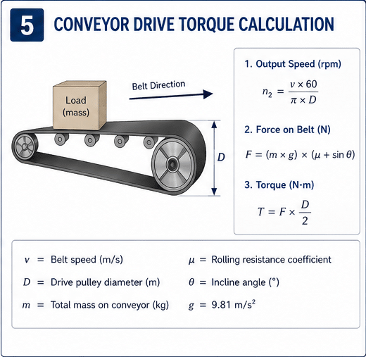
Step 2: Calculate Required Output Speed
Formula: n₂ = (v × 60) / (π × D)
Where:
- n₂ = Output speed (RPM)
- v = Belt speed (m/s)
- D = Pulley diameter (m)
- π = 3.14159
Example:
- Belt speed: 0.5 m/s
- Pulley diameter: 400mm = 0.4m
n₂ = (0.5 × 60) / (3.14159 × 0.4) n₂ = 30 / 1.257 n₂ = 23.9 RPM
Step 3: Determine Reduction Ratio
Formula: i = n₁ / n₂
Where:
- i = Reduction ratio
- n₁ = Motor speed (RPM)
- n₂ = Required output speed (RPM)
Example:
- Motor: 1400 RPM
- Required output: 23.9 RPM
i = 1400 / 23.9 i = 58.6
Select nearest standard ratio: 60:1
Actual output speed with 60:1: n₂ = 1400 / 60 = 23.3 RPM
Actual belt speed: v = (23.3 × π × 0.4) / 60 = 0.49 m/s ✓ (acceptable)
Step 4: Calculate Load Torque
Belt resistance torque:
T_belt = (F_belt × D) / 2
Where F_belt includes:
- Belt weight
- Material weight
- Friction losses
- Incline resistance (if applicable)
Simplified conveyor load calculation:
F_total = (m_belt + m_material) × g × (μ + sin θ)
Where:
- m_belt = Belt mass (kg)
- m_material = Material mass (kg)
- g = 9.81 m/s²
- μ = Friction coefficient (typically 0.02-0.04 for roller conveyors)
- θ = Conveyor angle (degrees)
Example:
- Belt: 500 kg total
- Material: 300 kg maximum
- Friction: 0.03
- Angle: 10° (sin 10° = 0.174)
- Pulley radius: 0.2m
F_total = (500 + 300) × 9.81 × (0.03 + 0.174) F_total = 800 × 9.81 × 0.204 F_total = 1,600 N
T_required = 1,600 × 0.2 = 320 Nm
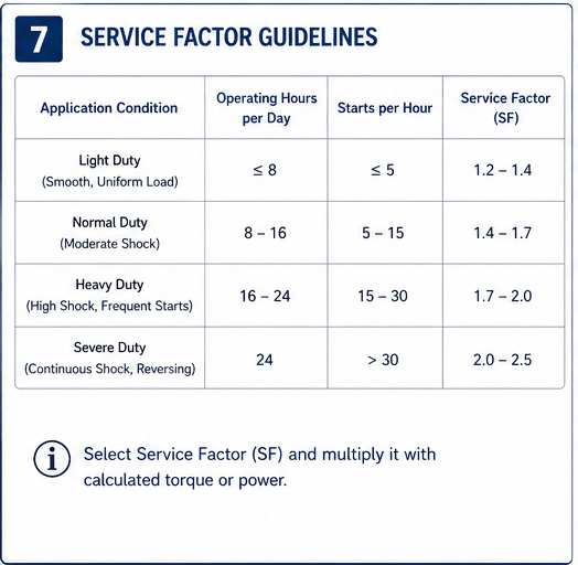
Step 5: Apply Service Factor
Service Factor Selection – Typical Values
⚠️ IMPORTANT: The following service factors are typical starting values based on industry experience. Actual service factors may need adjustment based on:
- Specific application details
- Manufacturing quality requirements
- Available safety margins in system
- Environmental severity
- Maintenance capabilities
| Application Type | Hours/Day | Starts/Hour | Typical Service Factor |
|---|---|---|---|
| Light packaging | <8 | <10 | 1.4 – 1.6 |
| Distribution center | 8-16 | 10-30 | 1.6 – 1.8 |
| Food processing | 16-20 | >30 | 1.8 – 2.0 |
| Mining/aggregates | 20-24 | Any | 2.0 – 2.5 |
| Reversing conveyor | Any | Any | 2.2 – 2.5 |
When to increase service factor beyond table values:
+0.2 to +0.3 additional if:
- Extreme temperature variations
- Heavy shock loads or impact
- Poor maintenance history
- Critical application (no backup)
- Abrasive or corrosive environment
+0.3 to +0.5 additional if:
- Emergency service (must-run application)
- Remote location (difficult maintenance access)
- Multiple severe conditions combined
Example:
- Food processing conveyor: Base service factor 1.8
- Add for critical application: +0.2
- Add for washdown environment: +0.2
- Total service factor: 2.2
Consult with gearbox manufacturer if:
- Service factor >2.5 required
- Multiple severe conditions present
- Application outside standard parameters
- Regulatory requirements impose additional safety margins
Note: These are industry-typical values. Your specific application may require different service factors based on detailed analysis of load profiles, duty cycles, and operating conditions.
Selection example: Food processing conveyor, 18 hrs/day, frequent starts
- Service factor: 1.8
T_design = 320 × 1.8 = 576 Nm
Step 6: Select Gearbox Model
With 60:1 ratio and 576 Nm required:
Check catalog ratings:
NMRV075 – 60:1:
- Rated torque: 520 Nm
- 576 Nm > 520 Nm ✗ (undersized)
NMRV090 – 60:1:
- Rated torque: 1,050 Nm
- 576 Nm < 1,050 Nm ✓
- Utilization: 55% (good margin)
Verify overhung load:
- Radial force: 2.5 × (576 / 0.2) = 7,200 N
- NMRV090 rating at 100mm: 1,800 N
- 7,200 N > 1,800 N ✗ (exceeds rating)
Solution: Use larger drive pulley:
- 500mm diameter instead of 400mm
- Radial force: 2.5 × (576 / 0.25) = 5,760 N
- Still exceeds 1,800 N rating
Better solution: NMRV110
- Overhung load rating: 2,800 N at 100mm
- Still marginal
Best solution: Upsize to NMRV110 with 500mm pulley
- Radial force: 2.5 × (576 / 0.25) = 5,760 N
- At 90mm distance: Rating increases
- Or add external bearing support
Final selection: NMRV110, 60:1 ratio
Step 7: Verify Motor Power
Required motor power calculation:
P_motor = (v × F_total × f_s) / (1000 × η_total)
Where:
- v = Belt speed (0.49 m/s)
- F_total = 1,600 N
- f_s = 1.8
- η_total = η_gearbox × η_drive
- η_gearbox = 0.60 (for 60:1 ratio, conservative)
- η_drive = 0.95 (belts/pulleys)
- η_total = 0.60 × 0.95 = 0.57
P_motor = (0.49 × 1,600 × 1.8) / (1000 × 0.57) P_motor = 1,411 / 570 P_motor = 2.48 kW
Select motor: 3 kW (next standard size above 2.48 kW)
Step 8: Verify Thermal Capacity
NMRV110 thermal rating: 5.5 kW continuous
Application: 3 kW motor input
- 3 kW < 5.5 kW ✓ (thermally adequate)
If thermal capacity inadequate:
- Upsize gearbox for better heat dissipation
- Add cooling fan
- Use synthetic oil (better heat transfer)
- Reduce duty cycle
Application-Specific Considerations
Food Processing Conveyors
Requirements:
- NSF H1 food-grade lubricants
- Washdown-rated seals (IP66 or IP69K)
- Stainless steel hardware
- FDA-compliant materials
Recommended configuration:
- NMRV series with epoxy paint
- Viton seals (chemical resistant)
- Stainless steel nameplate and fasteners
- Sealed breather (IP66)
Lubricant:
- Food-grade synthetic (NSF H1)
- Common options: Castrol Optileb HY, Shell Cassida GL, Klüber Unisilkon GLT
Maintenance:
- Daily visual inspection for leaks
- Weekly seal inspection
- Monthly breather cleaning
- Oil change every 5,000 hours (or annually)
Mining and Aggregate Conveyors
Environment:
- Heavy dust and abrasive particles
- Shock loads from material impact
- Temperature extremes
- Outdoor exposure
Protection measures:
- Double-lip seals (dust exclusion)
- Labyrinth seal on input shaft
- Protected breather with filter element
- Heavy-duty powder coat finish
Gearbox selection:
- Cast iron housing (WP series) for shock resistance
- Oversized bearings
- Service factor 2.0× minimum
- Shaft seals: Nitrile with garter spring
Belt cleaning critical:
- Material buildup on return rollers increases load
- Clean belt reduces power requirement 15-25%
- Scraper positioning affects drive load
Inclined Conveyors
Additional considerations:
Self-locking verification:
- Request manufacturer certification for specific model and ratio
- Test under actual load conditions
- Never rely on self-locking alone
⚠️ Self-Locking and Brake Requirements
CRITICAL SAFETY PRINCIPLE:
Self-locking should NEVER be the sole safety mechanism for:
- Personnel-carrying conveyors
- Overhead conveyors
- Inclined conveyors >15° angle
- Applications where back-driving creates injury risk
- Valuable or hazardous materials
Engineering safety hierarchy:
Level 1: Mechanical backstop or brake (PRIMARY)
- Independent of gearbox
- Fail-safe design
- Regular inspection and testing
- Examples: Spring-set brake, ratchet backstop
Level 2: Verified self-locking (SECONDARY)
- Manufacturer certification
- Load testing verification
- Regular functional testing
- Monitoring system
Level 3: Electrical control (TERTIARY)
- Power-off detection
- Automatic brake activation
- Emergency stop systems
Correct design approach:
Low-risk inclined conveyor (materials only, <10°):
- Self-locking gearbox (verified): May be acceptable
- Regular testing required
- Warning signs about back-driving risk
Medium-risk inclined conveyor (valuable products, 10-20°):
- Self-locking gearbox (verified): PLUS
- Mechanical backstop or brake: REQUIRED
- Testing before each shift
High-risk inclined conveyor (personnel, >20°, hazardous materials):
- Mechanical brake (fail-safe): REQUIRED
- Self-locking gearbox: Additional safety layer
- Monitoring and alarm system: REQUIRED
- Redundant safety systems
Correct statement: “Self-locking capability can provide an additional safety layer, but verified mechanical braking or backstop devices are required for applications where back-driving creates safety hazards.”
Liability and regulatory considerations:
- OSHA regulations may require mechanical brakes
- Insurance requirements
- Industry standards (CEMA, ISO)
- Local safety codes
Cost comparison:
- Spring-set brake: $400-1,200
- Backstop device: $300-800
- Cost of accident: $50,000-$5,000,000+
The engineering decision is clear: Install proper braking/backstop devices for any application with safety implications.
Startup torque increased:
- Gravity component adds to friction resistance
- Service factor increase 0.2-0.3 for each 15° angle increase
Belt tension monitoring:
- Inclines require higher belt tension
- Affects drive torque calculation
- Verify with belt manufacturer specs
Reversing Conveyors
Bidirectional operation challenges:
Worm gear considerations:
- Efficiency differs by direction
- Forward (worm drives wheel): Normal efficiency
- Reverse (wheel drives worm): Lower efficiency
- Some ratios won’t reverse at all (self-locking)
Service factor:
- Minimum 2.0× for reversing applications
- Accounts for direction change shock loads
Bearing selection:
- Must handle thrust in both directions
- May require bearing upgrades
Lubrication:
- Reversing creates different oil distribution
- Verify adequate lubrication both directions
Recommended: Use ratio <30:1 for reliable reversing
Installation and Commissioning
Alignment Requirements
Belt tracking depends on alignment:
- Gearbox to drive pulley: ±0.1mm parallel offset maximum
- Angular misalignment: ±0.1° maximum
- Use laser alignment tools for precision
Mounting base:
- Flat within ±0.05mm
- Rigid (no flexing under load)
- Grouted if concrete foundation
Belt Tensioning
Proper tension critical:
- Too loose: Belt slippage, increased wear
- Too tight: Excessive overhung load on gearbox
Tension verification:
- Measure belt deflection under load
- Typically 1-2% sag under finger pressure
- Use tension meter for accuracy
Run-In Procedure
First 100 hours:
- Operate at 70% load maximum
- Monitor temperature (should stabilize <80°C)
- Check for vibration or noise
- Verify belt tracking
Initial oil change: 200 hours
- Removes break-in wear particles
- Critical for long-term reliability
Temperature Monitoring
Establish baseline:
- Record housing temperature after 4 hours operation
- Typical: 55-75°C in 20°C ambient
- Create temperature log for trending
Warning signs:
- Temperature increase >15°C from baseline
- Indicates overload, misalignment, or lubrication problem
Maintenance Schedule for Conveyor Worm Reducers
Oil Change Intervals – Condition Dependent
These intervals assume normal operating conditions:
- Ambient temperature: 15-40°C
- Operating temperature: <80°C housing
- Clean environment (minimal contamination)
- Moderate duty cycle
- No shock loads
Mineral Oils:
- Standard duty: 2,500-4,000 hours
- OR 6 months, whichever comes first
Synthetic Oils (PAO-based):
- Standard duty: 5,000-8,000 hours
- OR 12-18 months, whichever comes first
Synthetic Oils (PAG-based):
- Standard duty: 8,000-10,000 hours
- OR 18-24 months, whichever comes first
⚠️ REDUCE intervals by 30-50% if:
High operating temperature:
- Housing >80°C continuous
- Ambient >40°C
- Poor ventilation
Heavy duty cycle:
- 20 hours/day operation
- Frequent starts/stops (>50/day)
- Shock loads or reversing
Harsh environment:
- Dusty conditions
- High humidity
- Chemical exposure
- Washdown applications
Example adjusted intervals:
Mining conveyor (dusty, 24/7 operation, high ambient):
- PAG synthetic: 5,000 hours (not 10,000)
- Oil analysis every 2,000 hours
Food processing (washdown, moderate duty):
- PAG synthetic: 6,000-8,000 hours
- Visual inspection daily
Indoor packaging (clean, 16 hrs/day):
- PAG synthetic: Full 10,000 hours possible
- Oil analysis at 5,000 hours to verify
⚠️ Oil analysis trumps time/hour intervals:
If oil analysis shows:
- Viscosity out of range
- High acid number
- Water contamination
- Metal particles
→ Change oil immediately regardless of hours/time
Engineering recommendation:
- Establish oil analysis program for critical applications
- Trend data over time
- Adjust intervals based on actual conditions
- Document change intervals and conditions
Routine Maintenance Tasks
Daily (during operation): ☐ Listen for unusual noise ☐ Visual check for oil leaks ☐ Verify normal operating temperature (touch test)
Weekly: ☐ Check oil level at sight glass ☐ Inspect seals for leakage ☐ Clean cooling fins if dusty
Monthly: ☐ Measure and record operating temperature ☐ Check mounting bolt torque ☐ Clean or replace breather filter ☐ Verify coupling alignment
Quarterly: ☐ Vibration analysis at bearing locations ☐ Infrared thermal imaging ☐ Belt tension verification ☐ Drain and inspect oil sample (if synthetic)
Annually: ☐ Oil change (mineral oils) ☐ Seal inspection and replacement if needed ☐ Bearing condition assessment ☐ Re-torque all mounting hardware ☐ Complete alignment verification
Every 2-3 years: ☐ Oil change (synthetic oils – condition dependent) ☐ Complete inspection and overhaul assessment
Common Problems and Solutions
| Problem | Probable Cause | Solution |
|---|---|---|
| Belt slipping | Insufficient tension | Increase belt tension |
| Worn pulley lagging | Replace pulley covering | |
| Excessive temperature | Overload condition | Verify actual load, upsize if needed |
| Low oil level | Check and refill to correct level | |
| Poor ventilation | Clean fins, improve airflow | |
| Belt tracking issues | Misalignment | Realign gearbox to drive pulley |
| Uneven belt tension | Adjust tension evenly both sides | |
| Gearbox noise | Bearing wear | Replace bearings |
| Misalignment | Correct alignment | |
| Oil leaks | Failed shaft seal | Replace seal, check alignment |
| Over-filled oil | Drain to correct level | |
| Clogged breather | Clean or replace breather | |
| Belt won’t start | Insufficient motor torque | Check motor, verify sizing |
| Seized gearbox | Check oil, inspect internals | |
| Material jam | Clear obstruction |
When to Upsize Beyond Calculation
Consider larger gearbox even if calculations adequate:
Future expansion:
- Conveyor speed increase planned
- Belt width increase anticipated
- Additional load capacity needed
Harsh conditions:
- Extreme temperatures
- Heavy contamination
- Limited maintenance access
Critical application:
- Production bottleneck
- No backup conveyor
- High cost of downtime
Upsize = insurance against:
- Calculation errors
- Unexpected load increases
- Extended service life
- Cooler operation (less wear)
Cost analysis: One frame size larger typically costs 15-25% more but can double service life from 5 to 10+ years.
Direct Factory Sourcing Advantages
Working directly with gearbox manufacturers provides:
Custom configurations:
- Special flange patterns
- Extended shafts
- Custom paint/coating
- Modified sealing for environment
Technical support:
- Application engineering assistance
- Detailed calculations and verification
- CAD drawings and 3D models
- Installation and commissioning support
Documentation:
- Complete torque tables
- Efficiency curves by ratio
- Thermal capacity charts
- Maintenance manuals
Quality assurance:
- Factory testing and certification
- Traceable materials
- ISO 9001 quality systems
- Warranty and support
Summary
Successful worm gear reducer for conveyor specification requires systematic approach:
- Define operating parameters – Speed, load, duty cycle, environment
- Calculate torque requirements – Account for all resistance sources, use complete overhung load formula
- Apply appropriate service factor – 1.4-2.5× based on severity (typical values, adjust as needed)
- Select gearbox – Verify torque rating, overhung load, thermal capacity
- Verify efficiency – Use conservative efficiency values (ranges, not fixed)
- Size motor – Adequate power and starting torque
- Verify self-locking if required – Get manufacturer certification, never rely solely on ratio
- Install safety devices – Mechanical brakes/backstops for inclined applications
- Configure for environment – Seals, lubricants, coatings
- Install correctly – Alignment, tension, run-in
- Maintain systematically – Temperature, oil (condition-based intervals), seals, alignment
Critical engineering principles:
Thermal limiting: Worm gearboxes are typically thermally limited, not torque limited in continuous duty
Overhung load: Use complete calculation F = 2.0-2.5 × (T/r), not simplified F = T/r
Self-locking: Verify with manufacturer certification, install mechanical backup for safety applications
Efficiency: Use conservative range values, not fixed percentages
Service factors: Apply typical values with adjustments for specific conditions
The formula for success: Proper sizing + correct installation + systematic maintenance = 40,000-60,000 hour service life
For conveyor applications requiring detailed engineering analysis, custom configurations, or technical support, contact our application engineering team for professional sizing assistance and recommendations.