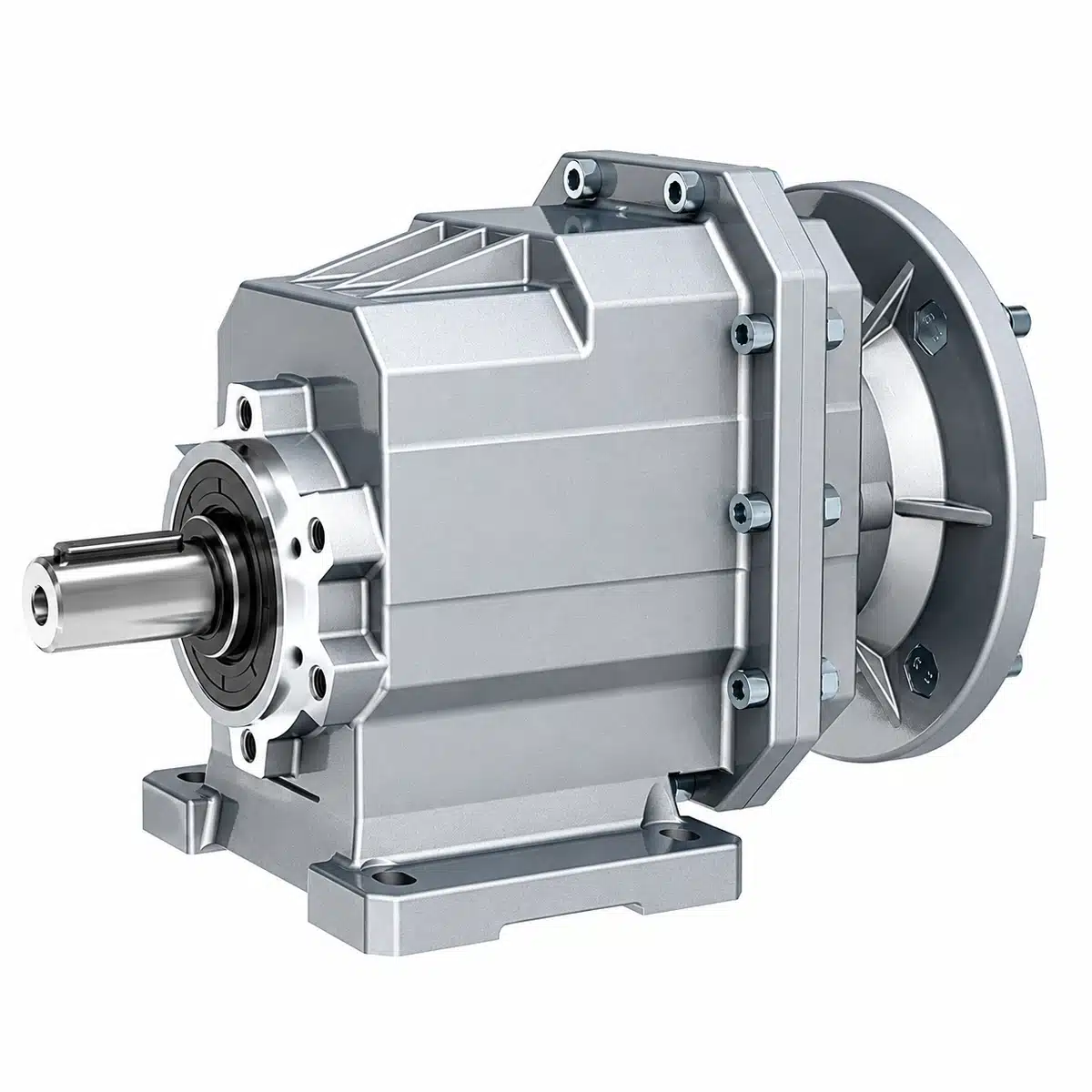
Description
TRC Series Helical Geared Motor
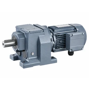
The TRC Series is our original compact inline helical geared motor platform for machinery requiring high transmission efficiency, low noise, a small installation envelope and flexible mounting. Six gear-unit sizes cover rated motor powers from 0.12 to 11 kW, nominal ratios from 3.66 to 58.78 and permissible output torque up to 1550 Nm.
Unlike a catalogue page that asks buyers to select only by motor power, a TRC geared motor should be selected as a complete drive system. Required output torque, output speed, service factor, radial load, mounting position, motor interface and installation dimensions should be checked together before the final model is confirmed.
Series Motor Power
Catalogue Ratio Range
Permissible Output Torque
Two-Stage Gear Efficiency
Request a TRC Selection and Quotation
Send us your required output speed, output torque, motor power, operating hours, starts per hour and mounting arrangement. Our engineers can recommend a technically matched TRC size, ratio, motor configuration and dimensional drawing.
TRC Series at a Glance
| Parameter | TRC Series Range |
|---|---|
| Gear Unit Sizes | TRC01, TRC02, TRC03, TRC04, TRC05, TRC06 |
| Series Motor Power | 0.12–11 kW |
| Nominal Gear Ratio | 3.66–58.78 |
| Permissible Output Torque | Up to 1550 Nm |
| Gear-Stage Efficiency | Approximately 96% |
| Gear Train | Two-stage helical gearing |
| Output Shaft Diameter | Ø20–Ø50 mm depending on gear-unit size |
| Mounting Forms | Foot, output flange and B14 flange |
| Input Configurations | Integrated geared motor, IEC motor adapter or solid input shaft |
| Mounting Positions | M1, M2, M3, M4, M5 and M6 |
| Motor Options | Standard, brake, inverter-duty, explosion-proof and application-specific motors |
| Housing | Lightweight aluminium housing |
Engineering note: These values describe the overall TRC catalogue envelope. Final permissible ratings depend on the exact gear ratio, motor power, service factor, mounting position and load condition.
Why Specify a TRC Helical Geared Motor?
Approximately 96% Gear-Stage Efficiency
The TRC uses a two-stage helical transmission with an approximate catalogue efficiency of 96%. Lower internal transmission losses help reduce heat generation, while actual complete-drive efficiency depends on motor efficiency, load and operating conditions.
Compact Inline Arrangement
The input motor and output shaft share an inline drive arrangement, making the TRC suitable for conveyors, packaging equipment and compact machines where the drive must fit along the driven shaft.
Quiet Helical Transmission
The helical gear arrangement provides gradual tooth engagement for smooth torque transmission and low operating noise, while the modular design supports multiple input and mounting configurations.
Six Mounting Positions
TRC geared motors can be specified for M1 through M6. The required mounting position must be stated when ordering because it determines lubricant quantity and installation configuration.
TRC Series Technical Selection Table — Power, Ratio, Torque & Motor Compatibility
Use this table for initial model screening. It combines the principal size-level data from the TRC performance and dimensional tables. Final selection must always be verified against the exact motor, ratio and service-factor combination.
| Size | Catalogue Motor Power* | Ratio Range | Output Speed @ 1400 rpm |
Max. Torque M₂max |
Max. Fr₂ | IEC Frame Range* | Mounting |
|---|---|---|---|---|---|---|---|
| TRC01 | 0.12–1.5 kW | 3.82–53.33 | 26–366 rpm | 120 Nm | 2600 N | 63–90 | M1–M6 |
| TRC02 | 0.18–2.2 kW | 3.66–54.00 | 26–383 rpm | 200 Nm | 4500 N | 63–90 | M1–M6 |
| TRC03 | 0.37–4.0 kW | 3.74–58.09 | 24–374 rpm | 300 Nm | 6000 N | 71–112 | M1–M6 |
| TRC04 | 0.55–4.0 kW | 3.74–58.09 | 24–374 rpm | 500 Nm | 8000 N | 80–112 | M1–M6 |
| TRC05 | 1.1–11 kW | 4.16–56.08 | 25–337 rpm | 820 Nm | 9000 N | 90–160 | M1–M6 |
| TRC06 | 1.1–11 kW | 4.71–58.78 | 24–297 rpm | 1550 Nm | 13000 N | 90–160 | M1–M6 |
Important: The motor-power and IEC-frame ranges above describe combinations appearing within the catalogue selection range. They do not mean that every motor power or IEC frame can be combined with every ratio.
The maximum torque shown is the size-level permissible mechanical torque M₂max. The rated output torque M₂n and service factor of the exact motor-ratio combination must be checked before ordering.
Permissible radial load Fr₂ also depends on output speed and load position. Recalculate the permitted load when a sprocket, pulley or gear acts away from the catalogue reference position.
TRC01–TRC06 Critical Dimensions for Machine Design & Installation
For machine layout, coupling selection and preliminary installation checks, the output shaft and flange dimensions below provide the most important size-level interfaces. Complete foot-mounting and motor-envelope dimensions should be confirmed from the dimensional drawing for the exact configuration.
| Model | Output Shaft | Shaft Extension | Output Key | Output Flange Options | IEC Motor Frames | Available Forms |
|---|---|---|---|---|---|---|
| TRC01 | Ø20 mm | 40 mm | 6 × 6 mm | Ø120 / Ø140 / Ø160 mm | 63–90 | Foot / Output Flange / B14 |
| TRC02 | Ø25 mm | 50 mm | 8 × 7 mm | Ø140 / Ø160 / Ø200 mm | 63–90 | Foot / Output Flange / B14 |
| TRC03 | Ø30 mm | 60 mm | 8 × 7 mm | Ø160 / Ø200 / Ø250 mm | 71–112 | Foot / Output Flange / B14 |
| TRC04 | Ø35 mm | 70 mm | 10 × 8 mm | Ø160 / Ø200 / Ø250 mm | 80–112 | Foot / Output Flange / B14 |
| TRC05 | Ø40 mm | 80 mm | 12 × 8 mm | Ø250 / Ø300 mm | 90–160 | Foot / Output Flange / B14 |
| TRC06 | Ø50 mm | 100 mm | 14 × 9 mm | Ø300 / Ø350 mm | 90–160 | Foot / Output Flange / B14 |
Dimensional selection note: Foot-mounting dimensions such as U, V, V1, V2, V3, W, X, X1, Y and Z vary with the selected foot or mounting configuration. Motor-envelope dimensions also change with IEC frame, motor length and brake option.
For replacement or machine-design projects, send us the required TRC size, motor frame, mounting form and mounting position. We can provide the corresponding dimensional drawing before production.
Need a Dimensional Drawing?
Send your required output shaft, flange or foot dimensions together with motor power and mounting position. We can verify the installation interface before the gearbox is ordered.
How to Select a TRC Series Helical Geared Motor
1. Define the Required Output Speed
Use the required machine speed to establish the target gearbox output speed.
where n₁ is the gear-unit input speed and n₂ is the required output speed.
For example, with a 1400 rpm input and required output speed of 95 rpm:
Select the nearest available catalogue ratio and then verify the resulting output speed.
2. Calculate Required Output Torque
When input power and output speed are known:
where M₂ is output torque in Nm, P₁ is input power in kW, η is transmission efficiency and n₂ is output speed in rpm.
Do not select a geared motor only from calculated running torque. Acceleration, shock load, operating hours and start/stop frequency must also be considered.
3. Determine the Application Service Factor
The TRC catalogue groups machine loads into three principal classifications:
| Load Class | Application Characteristic | Mass Acceleration Factor fa |
|---|---|---|
| A | Uniform load / low mass acceleration | ≤ 0.2 |
| B | Moderate shock load | ≤ 3 |
| C | Heavy shock load | ≤ 10 |
Required service factor depends on load class, daily operating time and start/brake cycles per hour. The service factor of the selected catalogue combination must meet the application’s calculated requirement.
4. Verify Rated Torque — Not Only Maximum Gearbox Torque
The torque shown in the size overview is the permissible mechanical limit M₂max. The rated output torque M₂n of a specific motor and ratio combination may be lower.
The selected catalogue combination must also provide the required service factor. This prevents a common selection error: choosing a large motor with a small gearbox simply because the headline maximum gearbox torque appears sufficient.
5. Check Radial and Axial Shaft Loads
Sprockets, pulleys and pinions create overhung load on the output shaft. The resulting radial load can be estimated using:
where M is shaft torque, d₀ is the mean diameter of the mounted transmission element and fz is the transmission-element factor.
| Transmission Element | Factor fz |
|---|---|
| Gear with 17 teeth or more | 1.00 |
| Gear with fewer than 17 teeth | 1.15 |
| Chain sprocket with 20 teeth or more | 1.00 |
| Chain sprocket with fewer than 20 teeth | 1.25 |
| Chain sprocket with fewer than 13 teeth | 1.40 |
| Narrow V-belt pulley | 1.75 |
| Flat-belt pulley | 2.50 |
| Toothed-belt pulley | 2.50 |
The catalogue permits axial load Fa = Fr₂ × 0.2 under its stated reference condition. Loads acting farther from the shaft shoulder reduce permissible radial capacity and must be recalculated.
6. Confirm Mounting, Shaft and Flange Dimensions
Confirm the output-shaft diameter and extension, key size, flange diameter, register, bolt pattern, foot arrangement and total geared-motor envelope before the model is finalized.
For an existing machine, dimensional compatibility should be checked from the installation drawing rather than from gearbox size alone.
7. State the Mounting Position and Terminal-Box Orientation
Specify M1–M6 and the required terminal-box orientation with the order. Changing the mounting position after delivery may require a different lubricant quantity and plug arrangement.
Worked TRC Selection Example
The original TRC catalogue provides a geared-motor selection example for an application requiring approximately 1 kW at the driven machine, 95 rpm output speed, eight operating hours per day and a calculated service factor of 1.35.
Required ratio:
Catalogue example power calculation:
The next standard motor rating is 1.5 kW. The catalogue example selects:
TRC02 – P90B5 – 14.81 – M6 – 1.5 kW – 4 pole
This example illustrates why a TRC geared motor should not be selected from motor power alone. Ratio, output speed, service factor, mounting position and valid motor interface must be checked together.
TRC Mounting and Input Configurations
| Configuration | Model Prefix | Typical Use |
|---|---|---|
| Foot-mounted gear unit / gearmotor | TRC | Mounted on a machine base or frame |
| Output-flange-mounted unit / gearmotor | TRCF | Gearbox centered and supported by the driven machine |
| B14 flange-mounted unit / gearmotor | TRCZ | Compact face-mounting installation |
| IEC motor-adapter gear unit | TRC..P(IEC) | For customer-supplied standard IEC motors |
| Solid-input-shaft gear unit | TRC..HS | External coupling, pulley or transmission drive |
| Integrated geared motor | TRC..MX | Factory-matched motor and gearbox package |
TRC Helical Geared Motor Applications
TRC compact inline geared motors are designed for continuous and cyclic industrial machinery requiring efficient inline power transmission, compact installation and flexible mounting.
- Belt conveyors
- Roller conveyors
- Chain conveyors
- Packaging machinery
- Labeling and filling equipment
- Food-processing machinery
- Textile machinery
- Automated storage systems
- Logistics and material handling
- Environmental-protection equipment
- Chemical-processing machinery
- Metallurgical auxiliary equipment
- Tobacco-processing machinery
- Automated production lines
Frequent reversing, high inertia, vertical lifting, human transport, explosive atmospheres and safety-related motion require application-specific engineering review. Standard catalogue selection alone is not sufficient for these duties.
Choose the Right Industrial Gearbox Configuration
TRC is optimized for compact inline drive applications. If your machine requires a different shaft arrangement or transmission principle, compare the other KB Transmission Star industrial gearbox families below.
| Drive Requirement | Recommended Series | Primary Arrangement |
|---|---|---|
| Compact inline machine drive | TRC Series | Compact two-stage inline helical |
| General-purpose inline industrial drive | R Series |
Inline helical |
| High-torque right-angle drive | K Series |
Helical-bevel |
| Compact right-angle helical-worm drive | S Series |
Helical-worm |
| Space-saving parallel-shaft drive | F Series |
Parallel-shaft helical |
Lubrication and Mounting Position
TRC gear units are supplied with lubricant for the ordered mounting position. The catalogue reference fill quantities are shown below.
| Size | M1 | M2 | M3 | M4 | M5 | M6 |
|---|---|---|---|---|---|---|
| TRC01 | 0.4 L | 0.6 L | 0.4 L | 0.3 L | 0.3 L | 0.3 L |
| TRC02 | 0.5 L | 0.7 L | 0.5 L | 0.4 L | 0.4 L | 0.4 L |
| TRC03 | 0.8 L | 1.1 L | 0.8 L | 0.6 L | 0.6 L | 0.6 L |
| TRC04 | 1.2 L | 1.6 L | 1.0 L | 1.0 L | 0.9 L | 0.9 L |
| TRC05 | 2.4 L | 3.0 L | 2.0 L | 2.1 L | 1.5 L | 1.5 L |
| TRC06 | 4.6 L | 5.5 L | 4.0 L | 4.4 L | 3.0 L | 3.0 L |
Lubricant quantities are catalogue reference values and may vary with the exact reduction ratio. Always confirm the final lubrication specification and ordered mounting position before commissioning.
OEM TRC Geared Motor Manufacturing & Configuration Support
As an industrial gearbox and geared-motor manufacturer in China, we support OEM buyers, distributors and machinery builders with drive selection, motor matching, dimensional confirmation and production configuration.
- IEC motor adapters and factory-matched geared motors
- Brake and inverter-duty motor configurations
- Special-voltage and application-specific motor options
- Foot, output-flange and B14 mounting
- M1–M6 mounting positions
- Terminal-box orientation selection
- Output shaft and flange configuration review
- Dimensional drawings and technical selection assistance
- Nameplate and packaging support for qualified OEM orders
Information Required for an Accurate TRC Quotation
For the fastest technical selection, send the following operating and installation information:
- Machine or application
- Required output speed in rpm
- Required running and peak torque in Nm, or driven-machine power in kW
- Motor power, voltage, frequency, phase and pole count
- Operating hours per day
- Starts, stops and reversals per hour
- Load type: uniform, moderate shock or heavy shock
- Foot, output flange or B14 mounting
- Mounting position M1–M6
- Output-shaft load and pulley, sprocket or pinion diameter
- Brake, VFD, explosion-proof or environmental requirements
- Required quantity and delivery destination
Get a Technical TRC Selection
Send us your operating data and installation requirements. We can recommend the TRC size, ratio, motor configuration and mounting arrangement and verify the critical dimensions before quotation.
Frequently Asked Questions
What is a TRC Series helical geared motor?
The TRC Series is an original compact inline geared-motor platform using two-stage helical gearing. It is available as a complete geared motor, an IEC motor-adapter gear unit or a solid-input-shaft reducer with foot, output-flange and B14 flange configurations.
What is the TRC Series motor power range?
The complete TRC Series covers catalogue motor powers from 0.12 to 11 kW. Individual gearbox sizes cover different portions of this range, and the permissible motor power depends on ratio, motor frame, service factor and configuration.
What ratios are available for TRC geared motors?
The complete catalogue ratio envelope is approximately 3.66 to 58.78. Individual sizes have different ranges: TRC01 3.82–53.33, TRC02 3.66–54.00, TRC03 and TRC04 3.74–58.09, TRC05 4.16–56.08 and TRC06 4.71–58.78.
What is the maximum output torque?
The six gear-unit sizes have permissible mechanical torque limits ranging from 120 Nm for TRC01 to 1550 Nm for TRC06. The actual rated output torque of the selected motor-ratio combination must be checked in the performance table.
How efficient is a TRC helical gearbox?
The TRC catalogue states approximately 96% transmission efficiency for its two-stage helical gearing. Complete geared-motor efficiency also depends on motor efficiency and the actual operating point.
Can a TRC geared motor be mounted vertically?
Yes. TRC gear units support M1 through M6 mounting positions. The required position must be specified when ordering so that lubricant quantity and installation configuration can be matched correctly.
Can I install my own IEC motor?
Yes. TRC P(IEC) adapter versions are available. Motor frame, flange, shaft dimensions, power, speed and the valid gearbox combination must be confirmed before ordering.
What output shaft sizes are available?
Standard output-shaft diameters increase with gearbox size: TRC01 Ø20 mm, TRC02 Ø25 mm, TRC03 Ø30 mm, TRC04 Ø35 mm, TRC05 Ø40 mm and TRC06 Ø50 mm.
How do I choose between TRC01 and TRC06?
Start with required output speed and torque, then verify service factor, permissible radial load, output-shaft size, flange or foot dimensions, motor compatibility and mounting position. Do not select a TRC size only from motor power or maximum gearbox torque.
Can TRC replace another compact helical geared motor directly?
Replacement suitability should be confirmed from the operating requirements and installation dimensions rather than assumed from a competitor model number. Send the existing nameplate, ratio, output speed, motor data, shaft dimensions, flange or foot dimensions, mounting position and application duty for an engineering cross-check.
Request Your TRC Series Selection
Reduce selection risk before the drive reaches your production line. Send the operating data and installation drawing to receive a recommended TRC size, ratio, motor, mounting configuration and dimensional confirmation.