Description
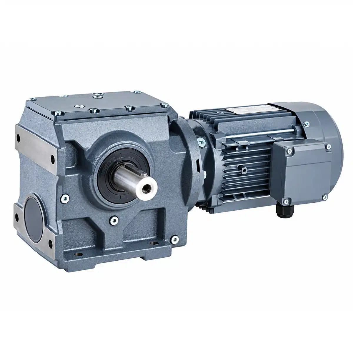
S Series Helical-Worm Gearbox & Geared Motor
Compact Right-Angle Drive with Helical + Worm Transmission
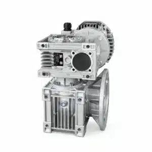
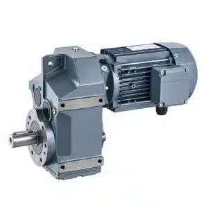
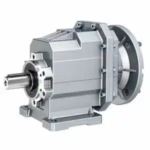
KB Transmission Star S Series Helical-Worm Gearboxes combine a high-efficiency helical pre-stage with a worm gear stage to provide compact right-angle power transmission, broad reduction ratios, smooth running characteristics and flexible mounting options.
Available in S37, S47, S57, S67, S77, S87 and S97 frame sizes, the series covers applications from compact conveying equipment to higher-torque industrial machinery.
Multiple output and mounting configurations are available, including solid shaft, hollow shaft, B5 flange, B14 flange and shrink-disc arrangements.
Key Technical Range
0.12–22 kW Motor Power
6.80–288.00 Standard Ratio Range
Up to 4,000 Nm Output Torque
S37–S97 Frame Sizes
M1–M6 Mounting Positions
Need Help Selecting an S Series Gearbox?
Send us your:
Motor Power + Input Speed + Required Output Speed + Torque + Mounting + Application
[REQUEST AN ENGINEERING QUOTE]
[SEND YOUR APPLICATION DATA]
Not sure which model you need? Send us your application and operating conditions. Our engineering team can help determine the appropriate S Series size, ratio, output configuration and motor.
S Series at a Glance
| Specification | S Series |
|---|---|
| Gear Technology | Helical + Worm |
| Output Arrangement | Right Angle |
| Frame Sizes | S37–S97 |
| Motor Power | 0.12–22 kW depending on size |
| Standard Ratio Range | 6.80–288.00 |
| Maximum Output Torque | Up to 4,000 Nm |
| Output Options | Solid Shaft / Hollow Shaft / Shrink Disc |
| Mounting Options | Foot / B5 Flange / B14 Flange |
| Mounting Positions | M1–M6 |
| Motor Connection | Geared Motor / IEC Motor Adapter |
| Main Applications | Conveyors, material handling, mixers, packaging and OEM machinery |
The published performance tables cover numerous motor-power, output-speed, ratio, torque and service-factor combinations across the series rather than one universal rating for every frame size.
What Is an S Series Helical-Worm Gearbox?
A conventional worm gearbox transmits power directly from a worm shaft to a worm wheel.
The S Series uses an additional helical reduction stage before the worm stage.
Standard Worm Gearbox
Motor
  ↓
Worm
  ↓
Worm Wheel
  ↓
90° Output
S Series Helical-Worm Gearbox
Motor
  ↓
Helical Gear Stage
  ↓
Worm Gear Stage
  ↓
90° Output
This combination allows the gearbox to achieve substantial speed reduction in a compact right-angle arrangement while retaining the smooth running characteristics associated with worm gearing.
The original catalog specifically describes the series as a helical-worm geared motor and provides seven principal gearbox sizes.
Why Choose an S Series Helical-Worm Gearbox?
Compact Right-Angle Transmission
The S Series changes the direction of power transmission by 90°, making it suitable for machines where the motor and driven shaft cannot be arranged inline.
Its compact architecture helps reduce overall machine space requirements.
Helical Pre-Stage + Worm Final Stage
The helical pre-stage provides an additional speed reduction before torque enters the worm stage.
This architecture gives designers greater ratio flexibility than a simple single-stage worm gearbox while maintaining a compact right-angle configuration.
Broad Reduction Ratio Coverage
Depending on frame size, standard S Series configurations cover reduction ratios from approximately:
6.80:1 to 288.00:1
Higher total ratios are available through selected multi-stage combinations, but these are treated separately from the standard S Series range.
Smooth & Quiet Operation
Progressive helical tooth engagement combined with the smooth meshing characteristics of the worm stage helps provide stable torque transmission and low-noise operation.
This makes the S Series suitable for conveyors, production machinery and other equipment operating for extended periods.
Multiple Output Configurations
The S Series is available with:
- Solid output shaft
- Hollow shaft
- Hollow shaft with flange
- Shrink-disc hollow shaft
- B5 flange
- B14 flange
This gives OEM engineers greater freedom when integrating the gearbox into different machine layouts.
S37–S97 Verified Technical Selection Guide
The following values are mapped from the original TS38–TS98 catalog performance data into the website S37–S97 naming system.
| Model | Motor Power Range | Standard Ratio Range | Maximum Output Torque | Solid Output Shaft |
|---|---|---|---|---|
| S37 | 0.12–1.1 kW | 6.80–157.43 | 92 Nm | Ø20 mm |
| S47 | 0.12–1.1 kW | 7.28–201.00 | 170 Nm | Ø25 mm |
| S57 | 0.12–3.0 kW | 7.28–201.00 | 295 Nm | Ø30 mm |
| S67 | 0.18–5.5 kW | 7.56–217.41 | 520 Nm | Ø35 mm |
| S77 | 0.37–9.2 kW | 8.06–256.47 | 1,270 Nm | Ø45 mm |
| S87 | 0.37–15 kW | 7.88–288.00 | 2,280 Nm | Ø60 mm |
| S97 | 0.75–22 kW | 8.26–286.40 | 4,000 Nm | Ø70 mm |
Important Engineering Note
The values above represent each frame size’s available catalog envelope.
They do not mean every motor power can be combined with every ratio or that every ratio can produce the maximum listed torque.
Final selection must consider:
Motor Power · Input Speed · Required Output Speed · Actual Output Torque · Service Factor · Radial Load · Mounting Position
The Performance Parameter portion of the source catalog provides those parameters as linked selection points rather than independent values.
S Series Critical Dimensions for Installation & Replacement
For replacement projects, gearbox ratio alone is not sufficient.
Critical mechanical dimensions should also be confirmed.
Solid-Shaft Critical Dimensions
| Model | Output Shaft | Shaft Extension | Key Width | Usable Key Length |
|---|---|---|---|---|
| S37 | Ø20 k6 | 40 mm | 6 mm | 32 mm |
| S47 | Ø25 k6 | 50 mm | 8 mm | 40 mm |
| S57 | Ø30 k6 | 60 mm | 8 mm | 50 mm |
| S67 | Ø35 k6 | 70 mm | 10 mm | 56 mm |
| S77 | Ø45 k6 | 90 mm | 14 mm | 80 mm |
| S87 | Ø60 m6 | 120 mm | 18 mm | 110 mm |
| S97 | Ø70 m6 | 140 mm | 20 mm | 125 mm |
Replacement Check
Before replacing an existing gearbox, confirm:
- Output shaft diameter
- Shaft extension
- Key size
- Foot mounting pattern
- Flange dimensions
- Hollow bore, if applicable
- Motor interface
- Output center position
- Installation orientation
Never assume dimensional interchangeability from the frame number alone.
[SEND YOUR EXISTING GEARBOX DRAWING →]
S Series Mounting & Output Configurations
The S Series provides multiple mechanical configurations for different machine designs.
S Series
Foot-Mounted, Solid Output Shaft
A conventional foot-mounted right-angle gearbox for base-mounted machinery.
Suitable for:
- conveyors
- processing equipment
- production machinery
- material handling systems
SF Series
B5 Flange-Mounted, Solid Output Shaft
Designed for direct flange installation where the gearbox is attached to the driven machine rather than mounted on a separate base.
SA Series
Hollow-Shaft Gearbox
Allows the gearbox to mount directly over the machine shaft, helping reduce couplings, external shaft connections and installation length.
SAF Series
Hollow Shaft with B5 Flange
Combines hollow-shaft mounting with a large B5 flange for secure direct machine integration.
SAZ Series
Hollow Shaft with B14 Flange
Provides a compact alternative flange arrangement for OEM machinery.
SH Series
Hollow Shaft with Shrink Disc
Provides a keyless friction connection between the gearbox hollow shaft and the driven machine shaft.
Suitable where secure shaft clamping and simplified removal are required.
SHF / SHZ Series
Shrink Disc with Flange Mounting
Combines shrink-disc output with B5 or B14 flange arrangements for more specialized machine layouts.
The catalog illustrates these multiple solid-shaft, hollow-shaft, flange and shrink-disc variants as distinct configurations.
Available Hollow-Shaft Configurations
Depending on frame size and configuration, multiple hollow-bore options may be available.
The dimensional drawings use H7 bore tolerances for hollow-shaft interfaces.
For replacement projects, always confirm:
Bore Diameter + H7 Tolerance + Keyway + Hollow-Shaft Length
rather than selecting only from the gearbox frame size.
Need a Hollow-Shaft Dimension?
Send us:
Model + Required Bore + Existing Shaft Diameter + Mounting Configuration
[REQUEST SA / SAF DIMENSIONS]
Standard S Series vs. Multi-Stage Combination
This distinction is important when selecting very high ratios.
Standard S Series
A standard S37–S97 unit consists of:
Helical Stage + Worm Stage
with standard ratios up to approximately 288:1, depending on frame size.
Multi-Stage Combination
For applications requiring extremely low output speed, selected S Series gearboxes can be combined with an additional reduction stage.
These combinations can achieve much larger total ratios.
Important
Do not select a standard S Series frame from a multi-stage ratio alone.
Contact engineering when:
- Required ratio exceeds the standard range
- Output speed is extremely low
- Starting torque is high
- Continuous operation is required
- Load inertia is significant
[ASK ABOUT HIGH-RATIO COMBINATIONS →]
Typical Applications
Conveyor Systems
S Series helical-worm geared motors are well suited to belt conveyors, roller conveyors and transfer systems requiring compact right-angle installation.
Material Handling
Suitable for industrial logistics, warehouse equipment, transfer systems and material movement machinery.
Packaging Machinery
The compact 90° drive arrangement allows the gearbox to be integrated into automated packaging, filling, labeling and conveying equipment.
Mixers & Processing Equipment
Higher-torque frames can be selected for mixing, processing and other equipment requiring low-speed right-angle output.
Food Processing Equipment
Suitable for conveyors and processing machinery where compact installation and stable operating speed are required.
OEM Industrial Machinery
Multiple output-shaft and mounting configurations make the S Series particularly useful for machinery manufacturers requiring flexible gearbox integration.
How to Select an S Series Helical-Worm Gearbox
A correct gearbox selection should not be based on ratio alone.
Step 1 — Motor Power
Provide:
kW or HP
Example:
2.2 kW
Step 2 — Input Speed
Typical motor input speeds may include:
1400 / 1450 / 1750 rpm
depending on motor poles and operating frequency.
Step 3 — Required Output Speed
Approximate ratio:
i = Input Speed ÷ Output Speed
Example:
1400 ÷ 35 = approximately 40:1
Step 4 — Required Output Torque
The gearbox must provide sufficient permissible torque under actual operating conditions.
Do not assume the frame’s maximum catalog torque is available at every motor/ratio combination.
Step 5 — Service Factor
Consider:
- operating hours per day
- starts per hour
- load classification
- shock loading
- machine inertia
- ambient conditions
The catalog includes service factor, load classification and mass acceleration factor as part of the selection process.
Step 6 — Radial & Axial Loads
External loads must be checked when the output shaft directly carries:
- sprockets
- pulleys
- belt drives
- chain drives
The source catalog provides radial-load calculation methodology specifically for this reason.
Step 7 — Output Configuration
Select:
S / SF / SA / SAF / SAZ / SH / SHF / SHZ
according to how the gearbox connects to the machine.
Step 8 — Mounting Position
Confirm:
M1 / M2 / M3 / M4 / M5 / M6
Mounting position affects lubrication requirements and oil fill quantity.
Not Sure Which S Series Gearbox You Need?
You do not need to determine the complete model number yourself.
Send us:
Application: Belt Conveyor
Motor Power: 2.2 kW
Input Speed: 1450 rpm
Required Output Speed: 30 rpm
Mounting: Hollow Shaft
Operating Time: 16 hours/day
Quantity: 10 pcs
Our engineering team can evaluate:
Frame Size → Ratio → Output Torque → Service Factor → Output Configuration → Motor → Mounting Position
[SEND YOUR APPLICATION DATA]
Mounting Positions M1–M6
S Series gearboxes can be configured for different installation positions.
Correct mounting-position specification is important because it determines:
- Lubricant quantity
- Oil level
- Breather position
- Drain position
- Internal lubrication conditions
Engineering Note
For selected flange, hollow-shaft and shrink-disc configurations, mounting position and high input speed can increase lubricant churning losses.
Applications operating above approximately 2500 rpm input speed should therefore be confirmed with our engineering team.
When Requesting a Quote
Please specify:
M1 / M2 / M3 / M4 / M5 / M6
or send us an installation photo if you are unsure.
Lubrication for Reliable Operation
S Series helical-worm gearboxes use oil lubrication.
Mineral and synthetic gear oils can be selected according to:
- ambient temperature
- operating temperature
- gearbox size
- load
- mounting position
- application conditions
Oil Quantity Is Configuration-Dependent
The required lubricant quantity changes according to:
Frame Size + Mounting Position + Ratio + Gear Configuration
Therefore, S37–S97 should not be assigned one fixed oil capacity per frame size without identifying the exact mounting arrangement.
Important
Do not mix mineral and synthetic gear oils.
For lubricant recommendation, send us:
Gearbox Model + Ratio + Mounting Position + Ambient Temperature
Recommended Maintenance
A defined maintenance program helps maintain gearbox reliability and seal performance.
Initial Oil Change
Approximately:
300 operating hours
after initial commissioning.
Routine Inspection
Approximately every:
3,000 operating hours
or at least:
every 6 months
Check:
- lubricant condition
- oil level
- seals
- signs of leakage
- abnormal noise
- unusual temperature
Long-Term Maintenance
Depending on operating conditions, inspect and replace lubricant, bearing grease and sealing components as required.
High operating temperatures or demanding duty can shorten maintenance intervals.
Replacing an Existing Helical-Worm Gearbox?
If you already have an S Series, helical-worm or right-angle gearbox installed, send us the existing gearbox information.
Please Provide
Existing Brand
Model Number
Nameplate Photo
Motor Power
Gear Ratio / Output Speed
Output Shaft or Hollow Bore
Foot / Flange Dimensions
Mounting Position
Installation Photo
Our engineering team can evaluate an appropriate KB Transmission Star S Series configuration.
Dimensional and performance interchangeability must be verified before replacement.
[REQUEST A CROSS-REFERENCE]
S Series vs. Standard Worm Gearbox
| Feature | S Series Helical-Worm | Standard Worm Gearbox |
|---|---|---|
| Gear Structure | Helical + Worm | Worm + Worm Wheel |
| Output Direction | 90° | 90° |
| Reduction Architecture | Multi-stage | Primarily worm stage |
| Ratio Range | Broad | Broad |
| Solid Shaft | Available | Available |
| Hollow Shaft | Available | Commonly available |
| Flange Options | Multiple | Available |
| Shrink Disc | Available on selected configurations | Less common |
| Mounting Flexibility | High | High |
| Typical Use | Industrial machinery / conveyors / material handling | General speed reduction |
Which One Should You Choose?
Choose S Series when you need:
Helical-worm architecture + multiple mounting options + right-angle output + flexible hollow-shaft configurations
Choose a standard worm gearbox when:
simplicity, compact size and general-purpose speed reduction are the primary requirements.
For OEM Machinery Manufacturers
Developing a new machine?
Our engineering team can support selection according to:
- motor power
- input speed
- required output speed
- torque
- service factor
- mounting position
- output-shaft arrangement
- available installation space
For OEM projects, send machine drawings or drive-system requirements before final gearbox selection.
[START AN OEM PROJECT]
Why Work With KB Transmission Star?
Industrial Transmission Focus
KB Transmission Star focuses on industrial gearboxes and geared motors for OEM manufacturers, distributors and industrial users.
Engineering Selection Support
We evaluate:
Power · RPM · Ratio · Torque · Service Factor · Radial Load · Output Configuration · Mounting Position
instead of selecting a gearbox from ratio alone.
Multiple Gearbox Technologies
Our product portfolio includes:
- S Series Helical-Worm
- R Series Helical
- K Series Helical-Bevel
- F Series Parallel-Shaft Helical
- KKM Helical-Hypoid
- NMRV Worm Gear Reducers
- Double Reduction Gearboxes
This allows the drive architecture to be selected according to the application.
OEM & Distributor Support
Available support can include:
- Motor combinations
- Technical drawings
- Application selection
- OEM configurations
- Private labeling
- Export packaging
- Repeat-order supply
S Series Helical-Worm Gearbox FAQ
What is an S Series helical-worm gearbox?
An S Series gearbox combines a helical reduction stage with a worm gear stage to provide compact right-angle speed reduction. It is available in multiple frame sizes, ratios, output-shaft arrangements and mounting configurations.
What sizes are available?
The website range includes:
S37, S47, S57, S67, S77, S87 and S97.
What is the power range?
The complete S Series covers approximately:
0.12–22 kW
depending on gearbox size, ratio and motor combination.
What is the maximum S Series ratio?
Standard configurations reach approximately:
288:1
depending on frame size.
Selected multi-stage combinations can achieve higher overall ratios.
What is the maximum output torque?
The largest standard frame in this range, S97, has a catalog maximum output torque of approximately:
4,000 Nm
Actual permissible torque depends on ratio, motor power and application conditions.
What is the difference between S Series and a standard worm gearbox?
S Series uses:
Helical Stage + Worm Stage
while a conventional worm gearbox primarily uses:
Worm + Worm Wheel
The additional helical stage provides another reduction stage within the drive system.
Is a hollow-shaft version available?
Yes. SA, SAF, SAZ and SH configurations provide hollow-shaft options for different mounting requirements.
Is a shrink-disc version available?
Yes. Selected SH, SHF and SHZ configurations use a shrink-disc output arrangement.
Which mounting positions are available?
S Series gearboxes can be configured in:
M1–M6
mounting positions.
Does mounting position affect lubrication?
Yes. Mounting position affects oil quantity, oil level and the position of lubricant service components.
Can you help replace another gearbox brand?
Yes. Send the existing model, nameplate, motor data and critical installation dimensions. We can evaluate an appropriate S Series configuration.
What information is required for a quote?
Please provide:
Application, motor power, input speed, required output speed or ratio, torque if known, output arrangement, mounting position and quantity.
Request an S Series Gearbox Quote
Get an Engineering-Based Recommendation
Correct gearbox selection affects:
Operating Life · Temperature · Torque Capacity · Bearing Load · Reliability · Maintenance · Machine Uptime
Send us:
✓ Application
✓ Motor Power
✓ Input Speed
✓ Required Output Speed
✓ Required Ratio
✓ Required Torque
✓ Output Shaft / Hollow Bore
✓ Mounting Type
✓ Mounting Position
✓ Operating Hours
✓ Quantity
✓ Existing Gearbox Model, if replacing
[REQUEST ENGINEERING QUOTE]
Engineering selection support available for OEMs, distributors and industrial replacement projects.