
Gearbox Installation Guide: Prevent 40% of Failures with Correct Procedures
Installation errors cause 43% of premature gearbox failures in our field analysis—more than manufacturing defects, contamination, and overload combined. A precision-engineered worm gear reducer or helical gearbox can fail within weeks if mounted incorrectly.
In 20 years manufacturing industrial gearboxes, we’ve documented hundreds of installation-related failures. The pattern is consistent: misalignment destroys bearings in 2,000-5,000 hours instead of 40,000+, improper mounting warps housings and strips gears, wrong oil levels cause overheating and seizure.
This gearbox installation guide provides the specific procedures, tolerances, and checkpoints that prevent these failures. Whether installing NMRV worm reducers, helical gearboxes, or planetary units, these principles ensure maximum service life.
Pre-Installation Inspection and Preparation
Don’t skip this step. Pre-installation issues caught now take 5 minutes to fix. The same problems discovered after installation require hours of disassembly and reinstallation.
Visual Inspection
Check for shipping damage:
- Housing cracks or dents
- Bent or damaged shafts
- Damaged mounting flanges
- Missing nameplate or documentation
Rotate input shaft by hand:
- Should turn smoothly with consistent resistance
- No grinding, clicking, or binding
- No excessive play or wobble
If shaft won’t rotate or feels rough: Internal damage during shipping. Do NOT install. Contact supplier immediately.
Shaft and Flange Preparation
Remove protective coatings: Shafts and mounting flanges have rust-preventive coating applied at factory.
Removal method:
- Use clean solvent (mineral spirits, kerosene, or commercial degreaser)
- Wipe with lint-free cloth
- DO NOT use scrapers, files, or abrasive pads (damages precision surfaces)
- Verify shaft diameter with micrometer if coating was thick
Why this matters: Oil-based coatings prevent proper coupling fit and cause slippage. Paint overspray on flanges prevents flat mounting and causes misalignment.
Nameplate Verification
Verify these specifications before installation:
Model and ratio:
- Matches purchase order
- Correct for application requirements
- Input/output speeds calculated correctly
Power rating:
- Adequate for motor size
- Thermal rating suitable for duty cycle
Mounting position:
- Unit configured for intended orientation
- Oil fill matches mounting position
- Seals appropriate for mounting type
Example nameplate:
Model: NMRV090
Ratio: 50:1
Power: 4 kW
Mounting: B3 (horizontal foot mount)
Oil: ISO VG 320 - 1.2L
Mismatch discovered after installation = costly removal and replacement
Understanding Mounting Positions and Lubrication
Gearbox mounting position determines internal oil distribution and affects lubrication, thermal capacity, and torque rating. Installing a gearbox in wrong orientation causes immediate lubrication failure.
Standard Mounting Position Codes
B3 – Horizontal foot mount (most common):
- Feet down, shafts horizontal
- Standard oil level
- Full torque rating
- Best heat dissipation
B5 – Vertical flange mount:
- Motor flange on vertical surface
- Shafts horizontal
- May require oil level adjustment
- Slightly reduced thermal rating
B6 – Vertical foot mount:
- Feet on vertical wall
- Shaft pointing downward
- Special oil level requirements
- Reduced torque rating (typically 80-90%)
B7 – Vertical foot mount:
- Feet on vertical wall
- Shaft pointing upward
- Highest oil level needed
- May require double seals
B8 – Vertical mounting:
- Feet down, output shaft pointing upward
- Special sealing requirements
- Oil level critical
V5/V6 – Vertical shaft orientations:
- Input or output shaft vertical
- Requires additional oil
- Special seals mandatory
- Reduced ratings
Oil Level by Mounting Position
Critical: Oil level specifications in manual are position-specific.
B3 horizontal example:
- Oil level at center of sight glass
- Volume: 1.2L for NMRV090
V6 vertical example (output up):
- Oil level higher to reach upper bearings
- Volume: 1.8L for NMRV090 (50% more)
What happens with wrong oil level:
Too low:
- Upper bearings starve
- Worm mesh loses lubrication
- Temperature spikes within hours
- Bearing seizure in 100-500 hours
Too high:
- Excessive churning losses
- Oil foaming from aeration
- Pressure buildup forces oil past seals
- Efficiency drops 5-15%
Factory mistake we see repeatedly: Customer orders B3 horizontal mount. Receives unit with 1.2L oil. Installs in V6 vertical position without adding oil. Upper bearing fails in first week of operation.
Solution: Always verify mounting position before installation. Adjust oil level per manual for actual installation position.
Changing Mounting Position
If you must install in different position than ordered:
Step 1: Drain existing oil completely
Step 2: Determine new oil quantity from manual
- Find mounting position section
- Note required volume for new orientation
Step 3: Fill to correct level
- Add oil slowly through fill plug
- Check sight glass frequently
- Stop at specified level
Step 4: Verify seal configuration Vertical mounting often requires upgraded seals:
- Standard nitrile seals adequate for horizontal
- Vertical may need double-lip or Viton seals
- Contact manufacturer if changing to vertical
Precision Alignment – Critical for Bearing Life
Misalignment is the #1 installation error causing premature failure. Even 0.1mm offset or 0.1° angular error significantly reduces bearing life.
Types of Misalignment
Parallel (radial) misalignment:
- Shaft centerlines offset but parallel
- Creates radial load on bearings
- Causes vibration and seal wear
Angular misalignment:
- Shaft centerlines intersect but not parallel
- Creates axial thrust loads
- Causes coupling wear and shaft fatigue
Both types simultaneously:
- Most common real-world scenario
- Combines effects of both
- Accelerates all failure modes
Alignment Tolerances
Acceptable limits depend on shaft speed and coupling type:
Flexible coupling, <1000 RPM:
- Parallel offset: <0.10mm (0.004″)
- Angular: <0.15° (1.5mm per 100mm diameter)
Flexible coupling, 1000-3000 RPM:
- Parallel offset: <0.05mm (0.002″)
- Angular: <0.08° (0.8mm per 100mm diameter)
Rigid coupling, any speed:
- Parallel offset: <0.03mm (0.001″)
- Angular: <0.03° (0.3mm per 100mm diameter)
These are maximums, not targets. Actual alignment should be as close to zero as possible.
Alignment Tools and Methods
Straightedge and feeler gauge (rough alignment only):
- Acceptable for belt drives
- NOT adequate for direct coupling
- Use only for initial positioning
Dial indicator method (good):
- Measures offset and angularity
- Requires skill and experience
- Accuracy ±0.02mm possible
- Takes 20-30 minutes
Laser alignment (best):
- Real-time offset and angle display
- Provides shimming recommendations
- Accuracy ±0.01mm
- Takes 10-15 minutes
- Recommended for all direct-coupled applications
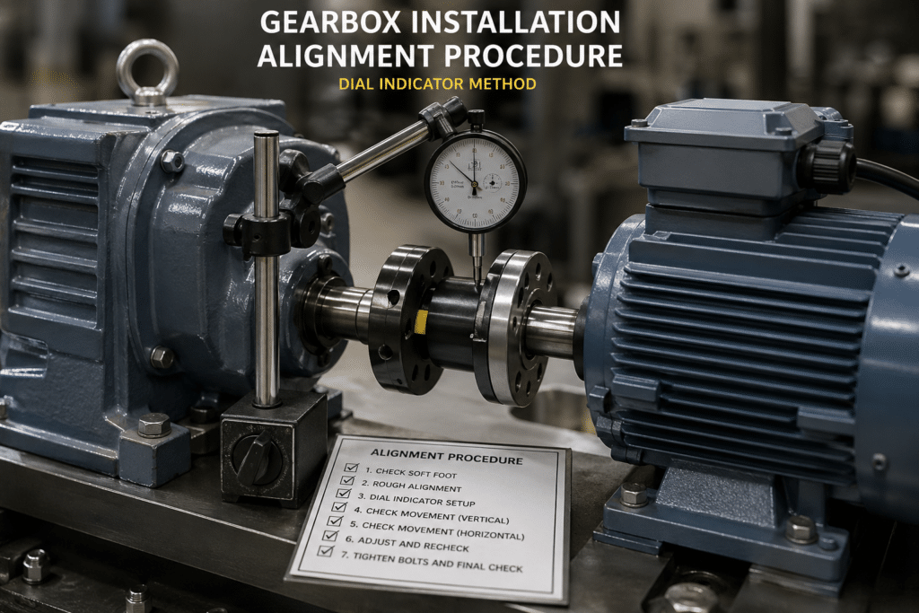
Alignment Procedure (Dial Indicator Method)
Step 1: Initial positioning
- Position gearbox approximately aligned
- Install coupling halves (don’t tighten fully)
- Verify adequate axial gap between coupling faces
Step 2: Mount dial indicators
- Indicator on rim (measures parallel offset)
- Indicator on face (measures angular)
- Or use single indicator rotated for both readings
Step 3: Rotate and record
- Rotate shaft 360° in 90° increments
- Record readings at 0°, 90°, 180°, 270°
- Compare readings to determine offset and angle
Step 4: Calculate corrections
- Parallel offset = (reading at 0° – reading at 180°) / 2
- Angular = difference between face readings
- Determine shim thickness and location
Step 5: Apply corrections and re-check
- Add/remove shims at motor feet
- Shift motor laterally if needed
- Re-measure until within tolerance
Step 6: Final verification
- Tighten all bolts to specification
- Re-check alignment (may change slightly)
- Adjust if necessary
Laser Alignment Procedure
Modern laser systems provide guided shimming:
- Mount laser transmitter and receiver
- Rotate shafts through measurement positions
- System calculates offset and angle
- Display shows shim thickness needed at each foot
- Apply shims and verify
Advantage: Eliminates calculation errors and reduces time by 50%.
Foundation and Mounting Surface Requirements
The best alignment means nothing if the mounting surface isn’t rigid and flat.
Flatness Requirements
Mounting surface flatness:
- Tolerance: ±0.05mm across entire base
- Check with precision straightedge and feeler gauge
- Uneven surface warps gearbox housing when bolts are tightened
What happens with warped housing:
- Internal bearing bores distort
- Bearings bind and run hot
- Gear mesh pattern shifts
- Teeth load unevenly (accelerated wear)
- Housing cracks from stress
Soft Foot Detection
Soft foot: One or more mounting feet don’t contact base fully
Detection procedure:
- Tighten all mounting bolts finger-tight
- Place dial indicator on shaft (vertical measurement)
- Loosen one bolt at a time
- Note shaft movement
- If shaft moves >0.02mm when loosening a bolt = soft foot at that location
Correction:
- Add shims under raised foot
- Re-check after shimming
- All feet should contact with <0.02mm variation
Foundation Rigidity
Mounting base must be rigid:
- Steel base plate: Minimum 12mm thick for <10kW, 20mm for >10kW
- Fabricated steel base: Must not flex under operating loads
- Concrete foundation: Properly cured, no cracks
Test for rigidity:
- Press down on gearbox with significant force
- Base should not deflect visibly
- Deflection allows misalignment during operation
Common problems:
Thin stamped steel base:
- Flexes under load
- Allows vibration
- Solution: Replace with thicker fabricated base or add cross-bracing
Unsealed concrete:
- Concrete dust contaminates oil through breather
- Solution: Seal concrete with epoxy paint
Ungrouted base plate:
- Gap between plate and foundation allows movement
- Solution: Grout under base plate after final alignment
Coupling and Drive Component Installation
Installing couplings, sprockets, pulleys, or gears onto shafts requires care. Impact damage destroys bearings immediately.
What NOT to Do
NEVER:
- Hit coupling onto shaft with hammer
- Use drift and hammer for installation
- Heat coupling and force onto shaft
- Install without cleaning shaft
- Overtighten set screws
Why hammering destroys gearboxes:
- Impact transmits through shaft to bearings
- Brinells bearing races (creates indentations)
- Damaged bearings fail within hours to weeks
- May damage internal circlips or retaining rings
We’ve replaced dozens of gearboxes where customer hammered on shaft during installation. Bearings destroyed before unit ever ran.
Correct Installation Methods
Method 1: Threaded hole draw-up (best for most couplings)
Most industrial gearboxes have threaded hole in shaft end.
Procedure:
- Clean shaft thoroughly
- Apply anti-seize to shaft surface
- Slide coupling onto shaft partially
- Insert bolt through coupling into threaded shaft hole
- Place washer under bolt head
- Tighten bolt to draw coupling onto shaft
- Remove bolt and install key
- Position coupling precisely
- Tighten set screws or split clamp
Method 2: Hydraulic press (for tight interference fits)
When shrink fit or press fit is required:
- Support gearbox output flange (NOT housing)
- Apply steady, even pressure
- Monitor force required
- Stop if excessive force needed (indicates problem)
Method 3: Thermal expansion (for heavy components)
For large sprockets or pulleys:
- Heat component to 80-100°C (heat gun or oven)
- DO NOT exceed 150°C (can affect hardness)
- Slide onto shaft quickly
- Allow to cool in position
- Verify position before full cooling
Key Installation
Parallel keys must fit properly:
Key width: Should slide into keyway with light finger pressure
- Too tight: Will bind and prevent proper seating
- Too loose: Allows fretting and wear
Key length:
- Should not bottom in keyway (leave 0.5-1mm clearance)
- Prevents key from taking axial loads
Key height:
- Should protrude slightly above shaft (0.1-0.3mm)
- Ensures coupling seats on key, not just shaft
Set Screw Tightening
Torque specifications critical:
Set screw size vs. torque:
- M4: 2.0 Nm
- M5: 3.5 Nm
- M6: 6.0 Nm
- M8: 14 Nm
- M10: 27 Nm
Common mistake: Over-tightening set screws
- Damages shaft threads
- Creates stress risers (fatigue failure initiation)
- Makes removal difficult
Use threadlocker (Loctite 243) instead of excessive torque
Anti-Seize Application
Apply anti-seize compound to shaft before installing components:
Benefits:
- Prevents fretting corrosion
- Allows future removal
- Reduces installation force
Application:
- Thin, even coat
- Avoid excess (contamination risk)
- Wipe surplus before coupling installation
Without anti-seize: Components can seize on shaft from fretting corrosion. May require destructive removal (cutting torch) after several years.
Mounting Bolt Installation
Incorrect bolt tightening is the second most common installation error after misalignment.
Bolt Selection
Use correct grade bolts:
- Metric: Grade 8.8 minimum (10.9 for high-load applications)
- Imperial: Grade 5 minimum (Grade 8 for high loads)
Never substitute lower-grade hardware:
- Grade 4.6 bolts will stretch and loosen
- Aluminum or brass bolts inadequate
- Mismatched threads strip easily
Torque Specifications
Without manufacturer specs, use these general guidelines:
| Bolt Size | Grade 8.8 Torque | Grade 10.9 Torque |
|---|---|---|
| M6 | 10 Nm | 12 Nm |
| M8 | 25 Nm | 30 Nm |
| M10 | 50 Nm | 60 Nm |
| M12 | 85 Nm | 100 Nm |
| M16 | 210 Nm | 250 Nm |
| M20 | 410 Nm | 490 Nm |
Tightening Sequence
ALWAYS tighten in star pattern:
4-bolt pattern:
- Tighten bolts opposite each other
- Sequence: 1-3-2-4
6-bolt pattern:
- Sequence: 1-4-2-5-3-6 (opposite pairs)
8-bolt pattern:
- Sequence: 1-5-3-7-2-6-4-8
Progressive tightening:
- First pass: 30% of final torque
- Second pass: 60% of final torque
- Final pass: 100% of final torque
Why star pattern matters:
- Even stress distribution
- Prevents warping
- Maintains alignment during tightening
Lock Washers and Thread Locking
Vibration causes bolt loosening over time
Prevention methods:
Lock washers:
- Split lock washers: Good for low-vibration
- Nord-Lock or similar: Better for high-vibration
Thread locking compound:
- Loctite 243 (blue): Removable, medium strength
- Loctite 271 (red): Permanent, high strength
- Apply to clean, dry threads before assembly
Nylock nuts:
- Nylon insert provides friction
- Good for applications without extreme heat
Annual maintenance: Re-torque all mounting bolts
Post-Installation Commissioning
Do NOT start at full load immediately. Run-in procedure ensures proper break-in and verifies installation.
Pre-Start Checks
Oil level verification:
- Check at sight glass with unit stationary
- Should be at center of sight glass (horizontal mount)
- Verify correct level for mounting position
Rotation direction check:
- Remove load from output
- Jog motor briefly (1-2 seconds)
- Verify output rotates correct direction
- CRITICAL for worm gears: Reverse rotation can occur with incorrect motor connections
Coupling guard installation:
- Ensure guards are in place
- Verify no interference with rotation
- Safety requirement before any operation
No-Load Run-In
First 30 minutes:
- Operate at no load or <25% rated load
- Monitor for abnormal sounds:
- Clicking: Bearing damage or loose component
- Grinding: Misalignment or contamination
- Squealing: Seal interference or belt issue
- Check for vibration
If any abnormal sounds occur: STOP immediately and investigate
Temperature Monitoring
After 2-4 hours of rated load:
Normal temperature rise:
- Worm gearboxes: 30-50°C above ambient
- Helical gearboxes: 25-40°C above ambient
- Planetary gearboxes: 20-35°C above ambient
Example:
- Ambient: 20°C
- Worm gearbox after 4 hours: 55-70°C (normal)
- Above 80°C: Investigate (likely overload, wrong oil, or misalignment)
Thermal imaging during run-in:
- Bearing areas should be slightly warmer than housing
- Hot spots indicate problems:
- One bearing much hotter: Misalignment or bearing damage
- Gear mesh area excessively hot: Wrong oil or overload
- Seal area hot: Excessive friction from misalignment
Oil Change After Break-In
First oil change: 100-500 hours (manufacturer specific)
Why early change is critical:
- Break-in wear generates fine metal particles
- Particles accelerate wear if not removed
- Fresh oil ensures clean operation
Procedure:
- Run gearbox to warm oil (easier draining)
- Drain completely
- Inspect drained oil for metal particles (normal in break-in oil)
- Refill with same grade oil to correct level
- Record date and hours for maintenance log
Troubleshooting Installation Issues
| Symptom | Probable Cause | Solution |
|---|---|---|
| Excessive vibration | Misalignment | Re-check alignment, correct as needed |
| Soft foot | Detect and shim soft feet | |
| Unbalanced drive component | Balance pulley/coupling | |
| High temperature | Overload | Verify load, upsize if needed |
| Wrong oil level | Adjust to correct level | |
| Poor ventilation | Clean fins, improve airflow | |
| Noise (grinding) | Bearing damage | Check for installation damage, replace |
| Contamination | Drain oil, flush, refill | |
| Noise (clicking) | Loose component | Check coupling, keys, bolts |
| Excessive backlash | Normal for worm gears unless severe | |
| Oil leaks | Shaft seal damage | Check for misalignment, replace seal |
| Over-filled | Drain to correct level | |
| Clogged breather | Clean breather | |
| Won’t rotate | Internal damage | Return to supplier |
| Wrong mounting position | Verify orientation and oil level |
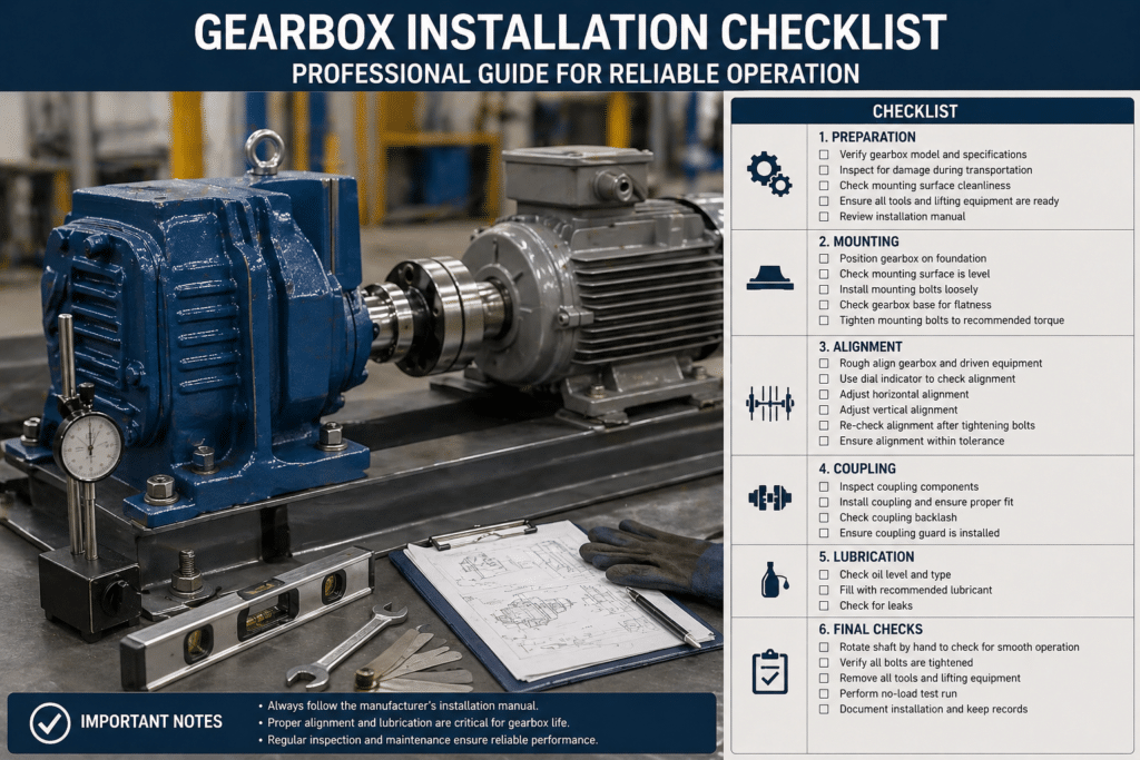
Installation Checklist
Pre-Installation: ☐ Visual inspection for damage ☐ Shaft rotates freely by hand ☐ Protective coatings removed from shafts ☐ Nameplate verified against requirements ☐ Correct mounting position confirmed
Mounting: ☐ Foundation flat within ±0.05mm ☐ Soft foot check completed ☐ All mounting feet contact base ☐ Bolts tightened in star pattern to spec ☐ Final torque applied to all bolts
Alignment: ☐ Parallel offset within tolerance ☐ Angular alignment within tolerance ☐ Final check after bolt tightening ☐ Documented alignment readings
Components: ☐ Shaft cleaned and anti-seize applied ☐ Keys properly fitted ☐ Couplings installed without impact ☐ Set screws torqued correctly ☐ Guards installed
Lubrication: ☐ Oil level correct for mounting position ☐ Breather vent clear ☐ No oil leaks visible
Commissioning: ☐ Rotation direction verified ☐ No-load run completed (30-60 min) ☐ Temperature monitored during initial run ☐ Break-in oil change scheduled
When to Contact Technical Support
Seek manufacturer assistance if:
- Unusual mounting position required
- Alignment tolerances cannot be achieved
- Application involves reversing loads
- Extreme ambient temperatures (<0°C or >50°C)
- High shock loads or frequent starts/stops
- Custom coupling or drive configuration
- Vibration issues persist after alignment correction
Our engineering team provides installation support including:
- Custom mounting drawings
- Alignment specifications for specific applications
- Commissioning assistance
- Vibration analysis and troubleshooting
Summary
Correct gearbox installation requires attention to five critical areas:
- Mounting position – Must match lubrication configuration
- Alignment – Within 0.05-0.10mm parallel, 0.08-0.15° angular
- Foundation – Flat within 0.05mm, rigid, no soft foot
- Component installation – No impact damage, proper torque
- Commissioning – Proper run-in and temperature verification
Installation errors cause 43% of premature failures. Following these procedures eliminates installation-related problems and ensures your gearbox delivers its full 40,000-60,000 hour design life.
For detailed installation drawings, torque specifications, and application-specific guidance, consult the technical manual supplied with your gearbox or contact our technical support team.